


3-11
Cisco VG224 Voice Gateway Hardware Installation Guide
OL-5006-04
Chapter 3 Installing the Cisco VG224 Voice Gateway
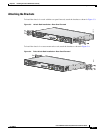
Bench-Top Installation
Bench-Top Installation
Step 1
Verify that there is a suitable AC power outlet available.
Caution
Do not plug this unit into an AC outlet that does not have a UL-certified receptacle that is properly tied
into building ground.
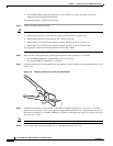
Step 2
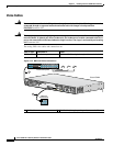
Place the four rubber feet (from the accessory kit) in the four indentations on the underside of the
chassis.This helps provide proper airflow through and around the chassis.
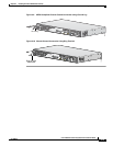
Step 3
Place the Cisco VG224 voice gateway on a smooth, flat surface.
Caution
Do not place anything on top of the chassis that weighs more than 10 lb (4.5 kg). Excessive weight on
top can damage the chassis.
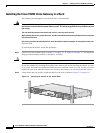
Installing the Ground Connection
Warning
This equipment must be grounded. Never defeat the ground conductor or operate the equipment in the
absence of a suitably installed ground conductor. Contact the appropriate electrical inspection
authority or an electrician if you are uncertain that suitable grounding is available.
Statement 1024
Warning
AC connected units must have a permanent ground connection in addition to the power cable ground
wire. NEBS-compliant grounding satisfies this requirement.
Statement 284
Warning
Use copper conductors only.
Statement 1025
You must connect the chassis to a reliable earth ground; the ground wire must be installed in accordance
with local electrical safety standards.
•
For NEBS-compliant grounding, use size AWG 6 (13 mm
2
) wire and the ground lug provided in the
accessory kit.
•
For NEC-compliant grounding, use size AWG 14 (2 mm
2
) or larger wire and an appropriate
user-supplied ring terminal.
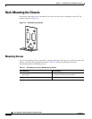
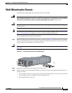
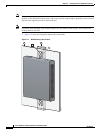
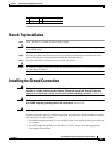
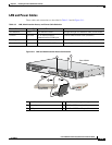
1 Wall 3 Wall stud
2 Bracket 4 Keyhole for starter screw