


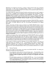
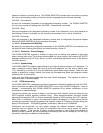


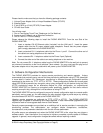
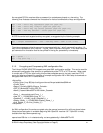

Figure 2 – PAP2 Front
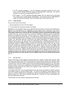
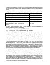
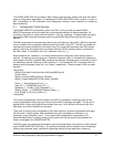
Figure 3 – PAP2 Back
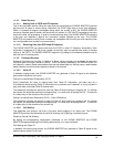
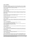
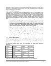
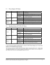
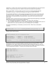
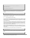
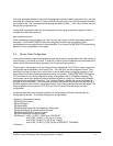
Figure 3 – RT31P2 Front Figure 4 – RT31P2 Back
The PAP2 PHONE ADAPTER has the following interfaces for networking, power and visual status
indication:
1. Two (2) RJ-11 Type Analog Telephone Jack Interfaces (Figure 3 , above):
These interfaces accept standard RJ-11 telephone connectors. An Analog touchtone telephone or
upports only one incoming line, the
rface (Figure 3, above):
his interface accepts a standard or crossover Ethernet cable with standard RJ-45 connector. For
nalog touchtone telephone or
nnected to port one (1) of the RT31P2. Port one (1) is
ve):
accepts a standard or crossover Ethernet cable with standard RJ-45 connector. For
optimum performance, Linksys recommends that a Category 5 cable or greater be used in
conjunction with the PHONE ADAPTER.
3. LEDs
fax machine may be connected to either interface. If the service s
analog telephone or fax machine should be connected to port one (1) of the PHONE ADAPTER. Port
one (1) is the outermost telephone port on the PHONE ADAPTER and is labeled “Phone 1.”
2. One Ethernet 10baseT RJ-45 Jack Inte
T
optimum performance, Linksys recommends that a Category 5 cable or greater be used in
conjunction with the PHONE ADAPTER.
The Broadband Router RT31P2 has the following interfaces for networking, power and visual status
indication:
1. Two (2) RJ-11 Type Analog Telephone Jack Interfaces (Figure 4, above):
These interfaces accept standard RJ-11 telephone connectors. An A
fax machine may be connected to either interface. If the service supports only one incoming line, the
analog telephone or fax machine should be co
the outermost telephone port on the RT31P2 and is labeled “Phone 1.”
2. Four (4) Ethernet 10/100 baseT, three (3) for Local Network and one (1) for Internet, all the 4 ports
uses RJ-45 Jack Interface, (Figure 5, abo
This interface
© 2004 Linksys Proprietary (See Copyright Notice on Page 2)
18