


96 Installation
Procedure 2
Wall-mounting the WLAN IP Telephony Manager 2245
Step Action
1
Use a 18-inch drill bit to dr ill four pilot holes, on 1.84 by 12.1 inch
centers (approximately equivalent to 1-1316 inch by 12-18 inch).
2
Insert the #8 x 34-inch screws in the pilot holes and tighten, leaving
a 18 to 14-inch gap from the wall.
3
Slide the WLAN IP Telephony Manager 2245 over the screws until
the WLAN IP Telephony Manager 2245 drops into place in the
keyhole openings of the flange.
4
Tighten screws fully.
—End—
Rack-mount
The rack-mount kit is designed for mounting the WLAN IP Telephony
Manager 2245 in a standard 19-inch rack and contains the following
equipment:
•
Mounting plates—two for each WLAN IP Telephony Manager 2245 to
be mounted.
•
Screws—four rack-mount screws for each WLAN IP Telephony Manager
2245 to be mounted.
Follow the steps in Procedure 3 "Rack-mounting the WLAN IP Telephony
Manager 2245" (page 96) to rack-mount the WLAN IP Telephony Manager
2245.
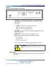
Procedure 3
Rack-mounting the WLAN IP Telephony Manager 2245
Step Action
1
Remove the corner screws from the WLAN IP Telephony Manager
2245.
2
Screw the U-shaped end (round screw holes) of the two mounting
plates to the WLAN IP Telephony Manager 2245.
3
Screw the other end of the two mounting plates (oblong screw holes)
to the rack.
Nortel Communication Server 1000
WLAN IP Telephony Installation and Commissioning
NN43001-504 01.02 Standard
Release 5.0 15 June 2007
Copyright © 2004-2007, Nortel Networks
.