Assembling the 4600 Series IP Telephone
Issue 6 February 2007 25
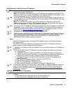
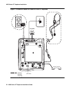
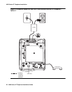
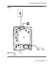
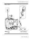
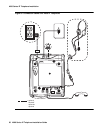
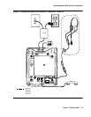
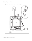
1. Plug one end of the H4DU 4-conductor coiled handset cord into the telephone and the other
end into the handset.
2. Plug one end of the first Category 5 modular line cord into the Ethernet jack of the PC and
the other end into the secondary Ethernet jack on the 4600 Series IP Telephone, if
appropriate.
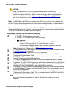
Note:
Note: The 4602SW/4602SW+ may have PC and LAN jacks reversed from their
pictures. Ensure that you make the right connections to the right equipment, as
noted by the icons on the telephone jacks.
3. Plug one end of the second Category 5 modular line cord into the Ethernet jack on the 4600
Series IP Telephone. Plug the other end of this cord into the Ethernet wall jack. If the
telephone is to be IEEE-powered, you are finished. Do not proceed to Step 4.
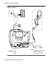
4. If the telephone is to be powered locally in the United States and Canada, plug the
power cord into the 4600 Series IP Telephone, and the power cord plug into the wall socket.
If the telephone is to be powered locally outside the United States and Canada,
connect the 1151 power brick to the power cable. Connect the other end of the power cable
to the 4600 Series IP Telephone, and the plug to the wall socket.


