


36 Freedom Sequence Intelligent Power Manager Owner’s Guide
Freedom Sequence Operational Concepts
DC Load Shedding
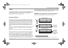
The Freedom Sequence continuously monitors the battery voltage and
compares it against the four voltage settings to set the trigger and clear the
trigger of a DC relay on a High Battery Voltage setpoint as well as a Low
Battery Voltage setpoint.
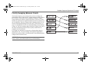
The Freedom Sequence power manager measures the battery voltage from
the DC power terminals of the auxiliary connector port. If Xantrex devices
exist on the Xanbus network, the power manager will use the battery
voltage reported by these devices in a preferential order by source as:
Battery monitor >> charge controller >> inverter/charger
The Trigger Set and Trigger Clear are absolute setpoints and don’t take into
account the duration for how long the battery voltage will be low before
triggering the DC relay. Each of the DC relays has a N/O and N/C contact
point which will toggle to Closed and Open positions respectively when a
DC relay is triggered.
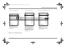
Using DC Relay to control AC load circuits
The DC Relays can also be used to shed AC load circuits if a DC Relay is
used to control the external AC Relay. This can be done by going to the DC
Relay configuration menu and selecting its association to Line1.
When the association is changed to Line1, all the configuration fields for
the DC relay will change to those found for the AC relay, allowing to define
Priority, Reconnect MRGN, Gen Soft-Start option, et cetera.
The Freedom Sequence does not have a current sensor to allow continuous
monitoring of the current draw by the load circuit that this DC relay
controls and therefore, it will show as N/A on the SCP.
However, the Freedom Sequence automatically calculates the decrease in
current achieved by disconnecting the AC load circuit that is indirectly
controlled through this DC relay and shows it as Last-Load Shed current.
FSequence IPM Owners Guide.book Page 36 Thursday, October 6, 2011 3:33 PM