


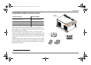
6 Freedom Sequence Intelligent Power Manager Owner’s Guide
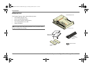
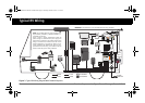
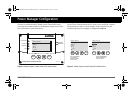
Typical RV Wiring
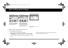
Figure 3
Typical RV Wiring Diagram With Freedom Sequence
INVERTER
SUBPANEL
GENERATOR
30A
FREEDOM SW
3012
FREEDOM
SW
3012
I
n
v
e
r
t
er
R
e
set
Enable
I
n
ve
r
t
e
r
A
C
/
On
C
ha
r
g
e
F
a
u
lt
Inverter/Charger
TO SHORE
CONNECTION
MAIN AC
PANEL
START
HOUSE
ALTERNATOR
ISOLATOR
12V FUSE
PANEL
B+ SIGNAL
DC RELAYS
AC 6
AC 5
AC 4
AC 3
AC 2
AC 1
DC RELAY 1
DC RELAY 2
BATT
DC AUX
HARNESS
AGS
TM
SCP
TM
50A
BATTERY
DC LINE
AC LINE AC DISCONNECT
XANBUS DC DISCONNECT
50A
300A
300A
A
A
NOTE: The Freedom Sequence power manager must
be permanently installed by a qualified installer in a
controlled environment.
Figure 3 shows a simple configuration where the
power manager is installed with a power supply line
(either shore or generator), one Freedom SW inverter/
charger, a Xanbus SCP, a Xanbus AGS, and various
electrical appliances in a typical RV. Means of over-
current protection and disconnection must be incor-
porated into the fixed wiring, in accordance with the
electrical code that governs each installation.
IMPORTANT: This illustration is not a detailed technical wiring schematic.
FSequence IPM Owners Guide.book Page 6 Thursday, October 6, 2011 3:33 PM