


975-0593-01-01 5
Mechanical Features
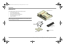
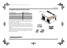
This section describes the different parts of the Freedom Sequence.
Ports and Terminals
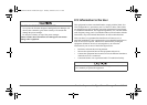
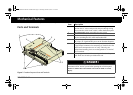
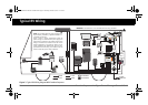
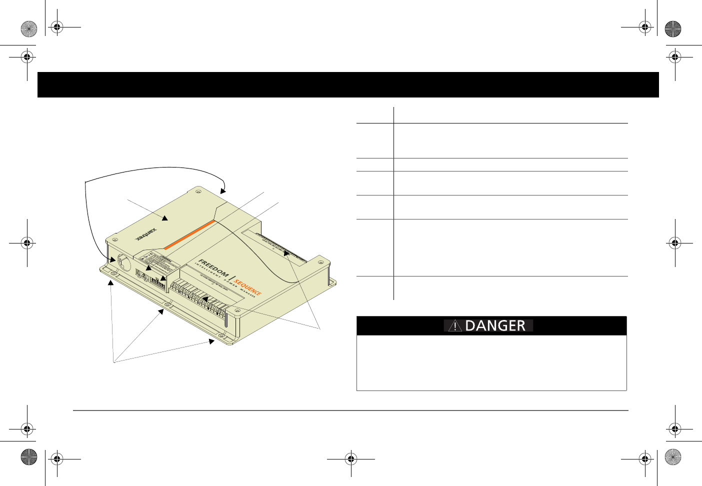
Figure 2
Freedom Sequence Ports and Terminals
1
3
5
4
6
2
Item Description
1 AC Main section contains the current and voltage sensors to
monitor the AC source and provides the pass-through wiring
from a transfer switch to the vehicle’s main distribution panel.
2 AC Main panel cover (removable for easy access)
3 Xanbus interface ports are used to connect Xanbus-enabled
devices including the SCP, AGS and Freedom SW.
4 DC auxiliary connector port contains the terminals for four
DC relays, B+ signal and DC power to the Freedom Sequence.
5 AC relay three-wire terminal blocks provide six (or four)
Cage Clamp® connectors for connecting AC load circuits. One
load circuit corresponds to one AC relay. The relays are
bidirectional meaning, there are no designated AC IN and AC
OUT terminals.
6 Mounting holes are used for mounting the Freedom Sequence
unit. There are six holes provided on the unit.
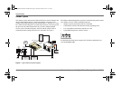
ELECTRICAL SHOCK HAZARD
Disconnect all DC and AC power before opening the AC Main panel.
Failure to follow these instructions will result in death or serious
injury.
FSequence IPM Owners Guide.book Page 5 Thursday, October 6, 2011 3:33 PM