


© 2003 Sipura Technology, Inc Proprietary (See Copyright Notice on Page 2)
4
1. Product Description
This guide describes basic administration and use of the Sipura Technology SPA-2000 phone
adapter – an intelligent low-density Voice over IP (VoIP) gateway. The SPA-2000 enables carrier
class residential and business IP Telephony services delivered over broadband or high-speed
Internet connections. By intelligent we mean the SPA-2000 maintains the states of all the calls it
terminates. It is capable of making proper decisions in reaction to user input events (such as on/off
hook or hook flash or enhanced services codes, i.e. *69) with little or no involvement by a middle-man
server or media gateway controller.
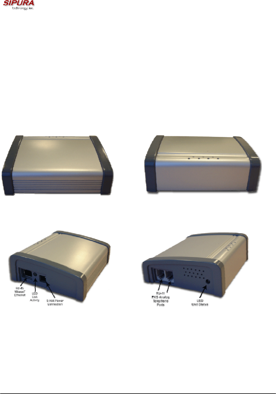
1.1. SPA-2000 Hardware Overview
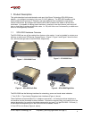
The SPA-2000 has one of the smallest form factors on the market. It can be installed in minutes as a
table-top or wall mount CPE device. Figures Figure 1, Figure 2, Figure 3 and Figure 5 show the front,
rear, left side and right side of the SPA-2000, respectively.
Figure 1 – SPA-2000 Front
Figure 3 – SPA-2000 Left Side
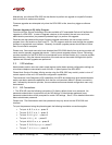
Figure 2 – SPA-2000 Rear
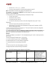
Figure 4 – SPA-2000 Right Side
The SPA-2000 has the following interfaces for networking, power and visual status indication:
1. Two (2) RJ-11 Type Analog Telephone Jack Interfaces (Figure 4, above):
These interfaces accept standard RJ-11 telephone connectors. An Analog touchtone telephone or
fax machine may be connected to either interface. If the service supports only one incoming line, the
analog telephone or fax machine should be connected to port one (1) of the SPA-2000. Port one (1)
is the outermost telephone port on the SPA-2000 and is labeled “Phone 1.”
2. One LED for Unit Status (Figure 4, above):