


Configuring the SDC 8000 system
98
Making a system diagnosis
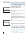
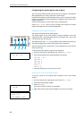
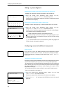
Displaying the number of consoles connected to the central unit
To display the number of consoles connected to the central unit:
̈ From the central unit’s operating menu, choose “
System”,
“
Diagnostics” and “Port Status” one after the other.
The ports P1 to P6 with their respective number of connected consoles
are shown on the display.
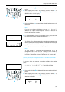
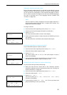
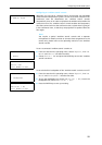
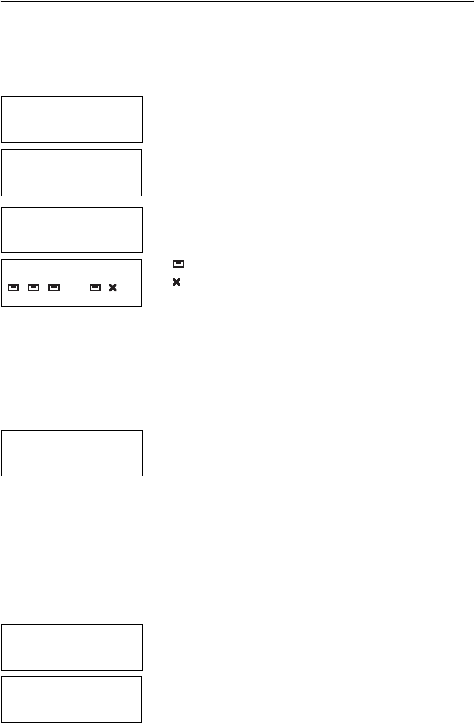
Checking the communication within a cable string
To display if and on which port(s) a communications error has occured:
̈ From the central unit’s operating menu, choose “
System”,
“
Diagnostics” and “Port Errors” one after the other.
The ports P1 to P6 with a respective symbol are shown on the display.
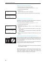
The symbols have the following meanings:
: A cable string with consoles is connected to the port.
: No cable string is connected to the port. If this symbol appears even
though a cable string is connected to the port, check if the cable string
is connected correctly.
[!]: A communications error has occured. This symbol only appears if
a cable string is connected to the port.
Configuring connected additional components
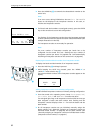
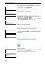
Camera control
If the license for your SDC 8000 conference and intepretation system
enables the “camera control” function, this function is already activated.
If this is not the case, no settings can be made via the “
Camera Control”
menu item.
Turning on a connected control panel
instead of controlling the SDC 8000 conference and interpretations system
via a PC with software control, you can use a control panel (optional).
The control panel is a miniature physical representation of your conference
room, allowing you to turn on or off individual conference consoles, change
the volume, change the conference mode, display the status of the
interpreter booths, etc.
The control panel will be custom tailored to your specific requirements.
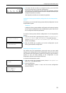
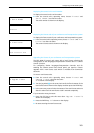
To turn a connected control panel on:
̈ From the central unit’s operating menu, choose “
System” and
“
Control Panel” one after the other.
The current status of the control panel is shown on the display.
̈ Choose “
Status = ON” and press the ENTER key to turn the control
panel on.
Diagnostics
1 Port Status
Port Status
15 15 14 02 15 15
P1 P2 P3 P4 P5 P6
Diagnostics
1 Port Errors
Port Errors
[!]
P1 P2 P3 P4 P5 P6
System
2 Camera Control
System
3 Control Panel
Control Panel
Status = OFF
Press ENTER to Save