Setting up the SDC 8000 system
51
Connecting PA systems, recording units, etc.
Via the audio outputs you can connect e.g. a PA system, a recording unit,
etc.
Connect the desired unit as follows:
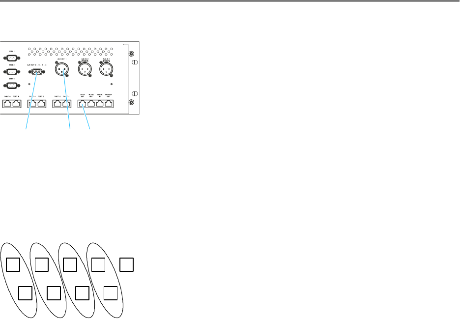
̈ The signals of the floor channel are available at the XLR-3M audio
output AUX OUT 1 µ and the 9-pole sub-D socket AUX OUT 2 ƺ.
̈ The signals of up to three interpretation channels are available at the
outputs AUX OUT 3-4-5 ƺ of the 9-pole sub-D socket.
̈ If an SDC 8000 AO analog output unit is connected to the DATA OUT
socket ƹ of the central unit, additional channels can be output via the
analog output unit’s XLR-3M audio outputs.
Pin assignment of the 9-pole sub-D socket (AUX OUT 2-3-4-5)
When connecting external equipment to the 9-pole sub-D socket (AUX
OUT 2-3-4-5 ƺ), please observe the following pin assignment:
PIN SIGNAL
1Aux Out 2
2Aux Out 3
3Aux Out 4
4Aux Out 5
5Not connected
6GND
7GND
8GND
9GND
The audio signal of the floor channel is always available at the two outputs
AUX OUT 1 (XLR-3M audio output) and AUX OUT 2 (pin 1 and 6 of the 9-
pole sub-D socket). This assignment cannot be changed!
The channel assignment for the three other audio outputs can be changed
as described in the section “Assigning a channel to an audio output” on
page 95. You can assign these outputs any interpretation channel or the
floor channel.
Note!
The audio signal of the channel assigned to the output AUX OUT 4 (pin
3 and 8 of the 9-pole sub-D socket) is also available at the headphone
output of the central unit!
Connecting an SDC 8000 AO analog output unit to the central unit
You can output additional interpretation channels via the SDC 8000 AO
analog output unit’s transformer balanced XLR-3M audio outputs or via
the unbalanced phono sockets next to the XLR-3 outputs.
To connect an analog output unit to the central unit:
ƺ
µ
ƹ
1 2 3 4 5
6 7 8 9


