


CHAPTER 4 CIRCUIT CARD INFORMATION
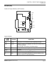
PN-DAID (DAI)
NEAX2000 IVS
2
Remote PIM System Manual
ND-70917 (E), Issue 1.0
Page 87
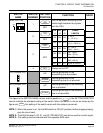
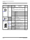
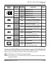
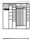
The figure in the SWITCH NAME column and the position in in the SETTING POSITION
column indicate the standard setting of the switch. When the switch is not set as shown by the
figure and , the setting of the switch varies with the system concerned.
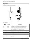
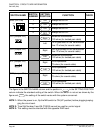
NOTE 1: Set the groove on the switch to the desired position.
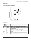
NOTE 2: When the power is on, flip the MB switch to ON (UP position) before plugging/unplug-
ging the circuit card.
SW3 (DIP SW) 1 Always set to ON
2 Always set to ON
3 Always set to ON
4 Always set to OFF
JPS (Jumper Pin) Balanced transmission:
120 ohms (for twisted-pair cable)
Left
TA is grounded on the transmission
line: 75 ohms (for coaxial cable)
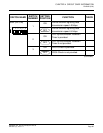
JPR (Jumper Pin) Balanced transmission:
120 ohms (for twisted-pair cable)
Left
RA is grounded on the transmission
line: 75 ohms (for coaxial cable)
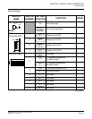
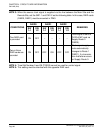
E1Z (Jumper Pin) Line impedance:
120 ohms (for twisted-pair cable)
Left
Line impedance:
75 ohms (for coaxial cable)
SRT (Jumper Pin)
Right
For mounting this card on PIM0
Left
For mounting this card on PIM1-
PIM7
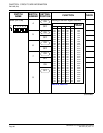
JP (Jumper Pin) Line impedance:
120 ohms (for twisted-pair cable)
DOWN
Line impedance:
75 ohms (for coaxial cable)
(Continued)
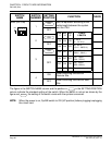
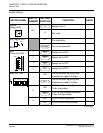
SWITCH
NAME
SWITCH
NUMBER
SETTING
POSITION
FUNCTION CHECK
1
2
3
4
ON
ON
ON
ON
ON
Right
Right
Right
UP