


CHAPTER 4 CIRCUIT CARD INFORMATION
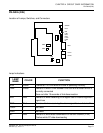
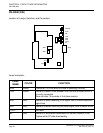
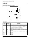
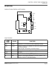
PN-DAIB (DAI)
NEAX2000 IVS
2
Remote PIM System Manual
ND-70917 (E), Issue 1.0
Page 79
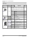
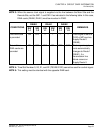
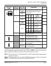
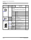
The figure in the SWITCH NAME column and the position in in the SETTING POSITION
column indicate the standard setting of the switch. When the switch is not set as shown by the
figure and , the setting of the switch varies with the system concerned.
NOTE 1: When the power is on, flip the MB switch to ON (UP position) before plugging/unplug-
ging the circuit card.
NOTE 2: Time Slot Number 0, 20, 21, and 22 (TS0/20/21/22) cannot be used for control signal.
NOTE 3: This setting must be identical with the opposite DAIA card.
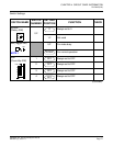
SWITCH
NAME
SWITCH
NUMBER
SETTING
POSITION
FUNCTION CHECK
SW3 (DIP SW)
1
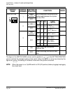
Set the equalizer according to the
cable length between the system
and the CSU.
OFF
2
OFF
3
OFF
4 Always set to OFF
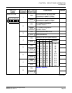
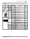
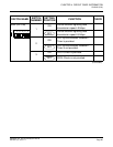
JPS (Jumper Pin)
UP
Neutral grounding on the
transmitting line is provided.
Neutral grounding on the
transmitting line is not provided.
JPR (Jumper Pin)
UP
Neutral grounding on the receiving
line is provided.
Neutral grounding on the receiving
line is not provided.
1
2
3
4
ON
ON
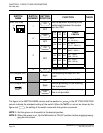
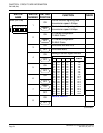
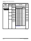
SW
-1
SW
-2
SW
-3
CABLE
LENGTH
ON ON ON
0 - 40 m
(0 - 131.2 ft.)
ON ON OFF
40 - 80 m
(131.2 - 262.5 ft.)
ON OFF ON
80 - 120 m
(262.5 - 394 ft.)
ON OFF OFF
120 - 160 m
(394 - 525 ft.)
OFF ON ON
160 - 200 m
(525 - 656 ft.)
OFF OFF OFF Signal is not sent.
ON
ON
OFF
DOWN
DOWN