


LIST OF FIGURES
Figure Title Page
NEAX2000 IVS
2
Remote PIM System Manual
ND-70917 (E), Issue 1.0
Page iii
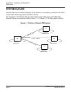
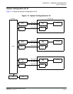
Figure 1-1 Outline of Remote PIM System . . . . . . . . . . . . . . . . . . . . . . . . . . . . . . . . . . . . . . . . . . 4
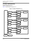
Figure 1-2 System Configuration for T1 . . . . . . . . . . . . . . . . . . . . . . . . . . . . . . . . . . . . . . . . . . . . 6
Figure 1-3 System Configuration for E1 . . . . . . . . . . . . . . . . . . . . . . . . . . . . . . . . . . . . . . . . . . . . 7
Figure 1-4 Time Slot Allocation for T1 (1 of 2) . . . . . . . . . . . . . . . . . . . . . . . . . . . . . . . . . . . . . . . 13
Figure 1-4 Time Slot Allocation for T1 (2 of 2) . . . . . . . . . . . . . . . . . . . . . . . . . . . . . . . . . . . . . . . 14
Figure 1-5 Time Slot Allocation for E1 . . . . . . . . . . . . . . . . . . . . . . . . . . . . . . . . . . . . . . . . . . . . . 15
Figure 2-1 Static Electricity Guard (1 of 2) . . . . . . . . . . . . . . . . . . . . . . . . . . . . . . . . . . . . . . . . . . 18
Figure 2-1 Static Electricity Guard (2 of 2) . . . . . . . . . . . . . . . . . . . . . . . . . . . . . . . . . . . . . . . . . .19
Figure 2-2 Installation Procedure for Main Site . . . . . . . . . . . . . . . . . . . . . . . . . . . . . . . . . . . . . . . 21
Figure 2-3 Installation Procedure for Remote Site . . . . . . . . . . . . . . . . . . . . . . . . . . . . . . . . . . . . 22
Figure 2-4 BUS Cable Connection (1 of 2) . . . . . . . . . . . . . . . . . . . . . . . . . . . . . . . . . . . . . . . . . . 24
Figure 2-4 BUS Cable Connection (2 of 2) . . . . . . . . . . . . . . . . . . . . . . . . . . . . . . . . . . . . . . . . . . 25
Figure 2-5 DAIA/DAID Between DAIA/DAID Cable Connection . . . . . . . . . . . . . . . . . . . . . . . . . . 26
Figure 2-6 DAIA/DAID Between DAIC/DAIF Cable Connection (1 of 2) . . . . . . . . . . . . . . . . . . . . 27
Figure 2-6 DAIA/DAID Between DAIC/DAIF Cable Connection (2 of 2) . . . . . . . . . . . . . . . . . . . . 28
Figure 2-7 DAIB/DAIE Between DAIC/DAIF Cable Connection . . . . . . . . . . . . . . . . . . . . . . . . . . 30
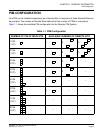
Figure 2-8 Mounting Location of Line/Trunk Card for T1 . . . . . . . . . . . . . . . . . . . . . . . . . . . . . . . 31
Figure 2-9 Location of Each LEN for T1 . . . . . . . . . . . . . . . . . . . . . . . . . . . . . . . . . . . . . . . . . . . . 32
Figure 2-10 LTC Connector Pin Arrangement for T1 (1 of 2) . . . . . . . . . . . . . . . . . . . . . . . . . . . . . 33
Figure 2-10 LTC Connector Pin Arrangement for T1 (2 of 2) . . . . . . . . . . . . . . . . . . . . . . . . . . . . . 34
Figure 2-11 Mounting Location of Line/Trunk Card for E1 . . . . . . . . . . . . . . . . . . . . . . . . . . . . . . . 35
Figure 2-12 Location of Each LEN for E1 . . . . . . . . . . . . . . . . . . . . . . . . . . . . . . . . . . . . . . . . . . . . 36
Figure 2-13 LTC Connector Pin Arrangement for E1 (1 of 2) . . . . . . . . . . . . . . . . . . . . . . . . . . . . . 37
Figure 2-13 LTC Connector Pin Arrangement for E1 (2 of 2) . . . . . . . . . . . . . . . . . . . . . . . . . . . . . 38
Figure 2-14 PFT Connection Outline (AUC) . . . . . . . . . . . . . . . . . . . . . . . . . . . . . . . . . . . . . . . . . . 39
Figure 2-15 MDF Cross Connection for PFT (AUC) (1 of 2) . . . . . . . . . . . . . . . . . . . . . . . . . . . . . . 40
Figure 2-15 MDF Cross Connection for PFT (PN-AUC) (2 of 2) . . . . . . . . . . . . . . . . . . . . . . . . . . . 41
Figure 2-16 PFT Connection Outline (8PFT) . . . . . . . . . . . . . . . . . . . . . . . . . . . . . . . . . . . . . . . . . 42
Figure 2-17 Connection of 25-Pair Cable and PZ-8PFTB . . . . . . . . . . . . . . . . . . . . . . . . . . . . . . . . 43
Figure 2-18 PFT Connector Pin Assignment . . . . . . . . . . . . . . . . . . . . . . . . . . . . . . . . . . . . . . . . . 44
Figure 2-19 MDF Cross Connection for PFT (8PFT) (1 of 2) . . . . . . . . . . . . . . . . . . . . . . . . . . . . . 45
Figure 2-20 MDF Cross Connection for PFT (8PFT) (2 of 2) . . . . . . . . . . . . . . . . . . . . . . . . . . . . . 46
Figure 2-21 DAI Cable Connection via LTC Connector (Main Site) . . . . . . . . . . . . . . . . . . . . . . . . 47
Figure 2-22 Example of DAI MDF Cross Connection via LTC Connector (Main Site) . . . . . . . . . . 48
Figure 2-23 DAI Cable Connection via CN Connector (Main Site) . . . . . . . . . . . . . . . . . . . . . . . . . 49
Figure 2-24 DAI Cable Connection via CN Connector (Remote Site) . . . . . . . . . . . . . . . . . . . . . . . 50
Figure 2-25 Outline of Optical Cable Connection . . . . . . . . . . . . . . . . . . . . . . . . . . . . . . . . . . . . . . 51
Figure 2-26 Example of M10 MDF Cross Connection via LTC Connector (Main Site) (1 of 2) . . . . 52
Figure 2-26 Example of M10 MDF Cross Connection via LTC Connector (Main Site) (2 of 2) . . . . 53
Figure 2-27 Example of M10 MDF Cross Connection via CN Connector (Remote Site) (1 of 2) . . 54
Figure 2-27 Example of M10 MDF Cross Connection via CN Connector (Remote Site) (2 of 2) . . 55
Figure 4-1 Mounting Location of Circuit Card . . . . . . . . . . . . . . . . . . . . . . . . . . . . . . . . . . . . . . . . 67