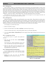
LBI-39169 MONITORING EDACS FAULT CONDITIONS
28
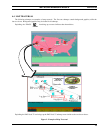
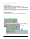
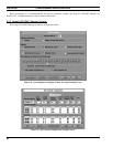
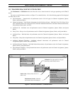
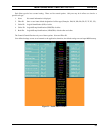
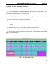
The user is able to determine the Managed Element’s operating condition at a glance by observing the icon’s color.
Upon receiving an alarm, the event is logged and the icon color is changed to the color representing the severity of the alarm.
To ensure alarms are not missed, the fault color propagates up to the top-level icon on the root map. The top level icon will
always reflect the color of the most severe fault propagated up from its submaps.
An EDACS Icon is managed if it has one of the following states: restricted, normal or alarm. The OpenView Help-
>Display Legend gives the association of state to color. An icon will be brown (indicating restricted) unless it has an
associated licensed IMC/CEC/RCEC/StarGate icon with the same EDACS Identifiers (Network Number and Node Number).
An EDACS icon will be blue if all of the elements on its submaps are restricted or unmanaged. An EDACS icon will also
be blue if there is another icon with the same EDACS identifiers. The last one added with those EDACS identifiers will be
managed.
An icon may be red if it is inaccessible from this Network Manager station. The EDACS->Fault->Summary menu item
will give a descriptive message regarding the state of the remote element.
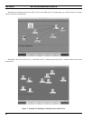
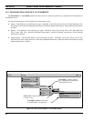
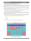
The Network Manager application counts the number of unique outstanding alarms at each severity level: Critical,
Major, Minor, Warning, and Normal. The icon color should be the same as the highest severity level and should not change
until all alarms at that severity level have cleared. When all alarms at the highest severity level have changed, the icon color
should change to the next lowest severity level.
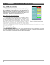
8.1.3 Fault Propagation
If there are no outstanding alarms, the icon color should correspond to the normal level. Icon color will propagate up the
hierarchical levels. There are options to propagate the most critical or the average alarm level. Select EDIT-
>Describe/Modify Map and set Map to Propagate Most Critical.
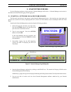
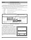
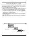
8.2 REPORTING FAULTS (ALARMS)
OpenView Network Node Manager provides choices for alarm propagation. The parent icon may be configured to
reflect the highest alarm state, an average alarm state, or a threshold.
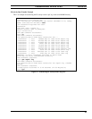
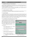
8.2.1 Fault Configuration
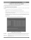
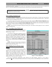
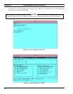
The
EDACS->Faults->Configuration
menu item generates the OpenView Network Node Manager Event Configuration
dialog box with an associated help button. This feature allows actions and popup windows to be associated with events,
modifications of the category, and severity level. However, it does not allow configuring the threshold-oriented alarms.
When configuring threshold-oriented traps at the Network Manager station, refer to the Options -> Data Collection menu
item. When configuring Threshold-oriented traps at a remote element, use the procedures in the section titled Setting
Threshold Traps On Collected Data.
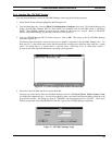
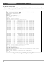
The action(s) to be performed following the receipt of an alarm is user-selectable on a per alarm basis. Multiple actions
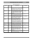
may be selected simultaneously. The list of possible actions is shown below.
•
Log the event with an entry describing the alarm, time of occurrence, source, and severity.
•
Display a popup window describing the alarm, time of occurrence, source, and severity.
•
Output to a printer describing the alarm, time of occurrence, source, and severity.
•
Execute a user-defined application resident on the EDACS NM or another network device via a remote procedure
call. This can include such tasks as issuing a data message to an EDACS data terminal, sending an e-mail message,
calling a pager, or making a telephone call.
•
Produce an audible beep.
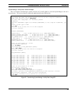
The EDACS NM application provides a default alarm definition, description, severity level, and category. The alarm
definition and descriptions can be restored to their default values by executing
/usr/OV/bin/xnmevents -load