


45
Network Configuration Quick Start
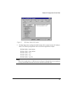
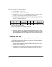
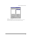
12. Using Output Word Select Data Pointer 0x04 to set the Index Deceleration Register and
Input Select Data Pointer 0x0A to read back this same parameter in order to verify the
transfer.
Final Word = XXX00100XXX01010
With zeros in for reserved bits Final Word = 1034 (0x40A)
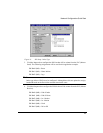
13. Set Output Bit O:1.1/0 high to initiate this incremental index.
14. Set Output Bit O:1/1/2 high and O:1.1/1 low to indicate an absolute index.
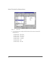
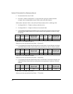
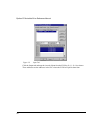
15. Using Output Word Select Data Pointer 0x01 to set the Index Distance/Position Register
and Input Select Data Pointer 0x07 to read back this same parameter in order to verify
the transfer.
Final Word = XXX00001XXX00111
With zeros in for reserved bits Final Word = 263 (0x107)
16. Set Output Bit O:1.1/0 high to initiate this absolute index.
Note
After the motion parameters have been configured (accel, decel, dist), these parameters
remain static until they are changed using either explicit messaging or the data select
pointers.
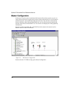
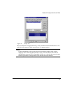
Example #4: Position Control
This sample procedure for the Position Controller Assembly Block will completely set up an
index and then initiate it using the addresses assigned in previous examples.
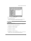
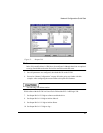
1. Start a new Ei-DN
configuration in PowerTools FM and configure the drive for the
particular motor that will be used. For more information consult the Epsilon Ei Drives
Reference Manual (P/N 400507-01.)
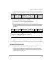
Reserved Reserved Reserved
Output Word Select
Data Pointer (See
page 15) = 0x04
Reserved Jog - Jog +
Input Word Select
Data Pointer (See
page 14) = 0x0A
XXX 00100 XXX 01010
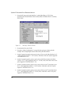
Reserved Reserved Reserved
Output Word Select
Data Pointer (See
page 15) = 0x01
Reserved Jog - Jog +
Input Word Select
Data Pointer (See
page 14) = 0x07
XXX 00001 XXX 00111