6
Epsilon Ei DeviceNet Drive Reference Manual
Connectors
DeviceNet connectors can be either open-style (wires exposed) or sealed. These connectors
can be obtained from the supplier of the DeviceNet Network Master. (For more details see
the ODVA Specification Volumes I and II, Release 2.0.)
Power Supply Requirements
A separate 24 VDC power supply is needed for the DeviceNet network. The Ei-DN slave
interface is powered using this “network power.” Devices may take all of their required power
off of the network per ODVA specifications.
The Ei-DN draws 25 mAmps from the DeviceNet power supply.
The power supply must have its own current limit protection.
Fuse protection must be provided for each segment of the cable system.
The power supply must be correctly sized to provide each device with its required power.
Power supplies should be distributed throughout the DeviceNet network to maintain a
maximum of 4 Amps per trunk branch.
For more details, refer to the ODVA Specification Volumes I and II, Release 2.0.
Terminating Resistors
Terminating resistors are used to reduce the reflection of signals over the network. Each
terminator must be 121 ohms and installed on both ends of the network between CAN_L (pin
2) and CAN_H (pin 3).
Electrical Installation
Physical Connections to the DeviceNet Network
A standard five wire configuration is used to connect the Ei-DN to the DeviceNet Network.
A 24 Volt power supply should be connected between V+ and V-.
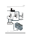
When multiple Ei-DN devices are present on the network, connection with all devices can be
accomplished by either daisy chaining or by using a multiple tap box.
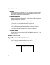
Pin Number Name Insulation Color
1 V- Black
2 CAN_L Blue
3DrainNone
4 CAN_H White
5V+Red


