


3-3
Cisco ATA 186 and Cisco ATA 188 Analog Telephone Adaptor Administrator’s Guide for MGCP (version 3.0)
OL-4803-01
Chapter 3 Configuring the Cisco ATA for MGCP
Specifying a Preconfigured VLAN ID or Disabling VLAN IP Encapsulation
3. Also from the DHCP server, the Cisco ATA requests the IP address of the TFTP server.
4. The Cisco ATA contacts the TFTP server and downloads the Cisco ATA release software that
contains the correct signaling image for the Cisco ATA to function properly.
Note If you are not using a TFTP server, you need to manually upgrade the Cisco ATA to the correct
signaling image. For information on this procedure, see the “Upgrading the Signaling Image
Manually” section on page 7-2.
5. The Cisco ATA looks for a Cisco ATA-specific configuration file (designated by the MAC address
of the Cisco ATA and named ata<macaddress> with a possible file extension) on the TFTP server
and downloads this file if it exists. For information about configuration file names, see the
“Configuration Files that the cfgfmt Tool Creates” section on page 3-13.
6. If the Cisco ATA does not find an ata<macaddress> configuration file, it looks for an atadefault.cfg
configuration file and downloads this file if it exists. This file can contain default values for the
Cisco ATA to use.
Note When the Cisco ATA is downloading its DHCP configuration, the function button on the top panel
blinks.
Specifying a Preconfigured VLAN ID or Disabling VLAN IP
Encapsulation
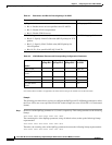
If you want the Cisco ATA to use a preconfigured VLAN ID instead of using the Cisco Discovery
Protocol to locate a VLAN, or if you want to disable VLAN IP encapsulation, refer to Table 3-1 for a
reference to the parameters and bits you may need to configure. Use the voice configuration menu to
configure these parameters. (See the “Voice Configuration Menu” section on page 3-20 for instructions
on using this menu.) Also, refer to Table 3-2 for a matrix that indicates which VLAN-related parameters
and bits to configure depending on your network environment.
Note Bits are numbered from right to left, starting with bit 0.