


2-5
Cisco ATA 186 and Cisco ATA 188 Analog Telephone Adaptor Administrator’s Guide for MGCP (version 3.0)
OL-4803-01
Chapter 2 Installing the Cisco ATA
Installation Procedure
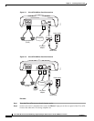
If you are connecting a telephone set that was previously connected to an active telephone line, unplug
the telephone line cord from the wall jack and plug it into the Phone 1 input.
Warning
To reduce the risk of fire, use only No. 26 AWG or larger telecommunication line cord.
Caution Do not connect the Phone input ports to a telephone wall jack. To avoid damaging the Cisco ATA or
telephone wiring in the building, do not connect the Cisco ATA to the telecommunications network.
Connect the Phone port to a telephone only, never to a telephone wall jack.
Note The telephone must be switched to tone setting (not pulse) for the Cisco ATA to operate properly.
Step 3 (Optional) Connect the telephone line cord of a second telephone to the Phone 2 input port.
Note If you are connecting only one telephone to the Cisco ATA, you must use the Phone 1 input port.
Step 4 Connect an Ethernet cable to the uplink RJ-45 connector on the Cisco ATA. For the Cisco ATA 186,
this is the 10BASE-T connector; for the Cisco ATA 188, this is the 10/100UPLINK connector.
Note Use a crossover Ethernet cable to connect the Cisco ATA to another Ethernet device (such as a router or
PC) without using a hub. Otherwise, use a straight-through Ethernet cable.
Step 5 (Cisco ATA 188 only—optional) Connect a straight-through Ethernet cable from your PC to the 10/100
PC RJ-45 connector on the Cisco ATA.
Step 6 Connect the socket end of the power cord to the Cisco-supplied 5V DC power adaptor.
Step 7 Insert the power adaptor cable into the power connector on the Cisco ATA.
Caution Use only the Cisco-supplied power adaptor.
Warning
This product relies on the building’s installation for short-circuit (overcurrent) protection. Ensure that
a fuse or circuit breaker no larger than 120 VAC, 15A U.S. (240VAC, 10A international) is used on the
phase conductors (all current-carrying conductors).
Step 8 Connect the plug end of the 5V DC power adaptor cord into an electrical power outlet.
When the Cisco ATA is properly connected and powered up, the green activity LED flashes to indicate
network activity. This LED is labeled ACT on the rear panel of the Cisco ATA 186 and is labeled LINK
on the rear panel of the Cisco ATA 188.
Caution Do not cover or block the air vents on either the top or the bottom surface of the Cisco ATA. Overheating
can cause permanent damage to the unit.