


2-4
Cisco ATA 186 and Cisco ATA 188 Analog Telephone Adaptor Administrator’s Guide for MGCP (version 3.0)
OL-4803-01
Chapter 2 Installing the Cisco ATA
Installation Procedure
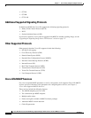
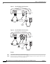
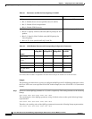
Figure 2-1 Cisco ATA 186 Rear Panel Connections
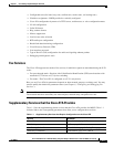
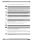
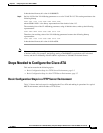
Figure 2-2 Cisco ATA 188 Rear Panel Connections
Procedure
Step 1 Place the Cisco ATA near an electrical power outlet.
Step 2 Connect one end of a telephone line cord to the Phone 1 input port on the rear panel of the Cisco ATA.
Connect the other end to an analog telephone set.
Power outlet
10BaseT ACT 5VPHONE 1 PHONE 2
72212
Analog telephones
(or fax)
5V power
adaptor
Power cord
IP network
10/100 UPLINK10/100 PC LINKLINK 5VPHONE 1 PHONE 2
Power outlet
72213
Analog telephones
(or fax)
5V power
adaptor
Power cord
PC
IP network