


3-2
Cisco ATA 186 and Cisco ATA 188 Analog Telephone Adaptor Administrator’s Guide for MGCP (version 3.0)
OL-4803-01
Chapter 3 Configuring the Cisco ATA for MGCP
Default Boot Load Behavior
• Cisco ATA Web Configuration Page, page 3-23—This section shows the Cisco ATA Web
configuration page and contains a procedure for how to configure Cisco ATA parameters using this
interface.
• Refreshing or Resetting the Cisco ATA, page 3-25—This section gives the procedure (via the Web
configuration page) for refreshing or resetting the Cisco ATA so that your most recent configuration
changes take effect immediately.
• Obtaining Cisco ATA Configuration File After Failed Attempt, page 3-26—This section gives the
formula for how soon the Cisco ATA attempts to fetch its configuration file from the TFTP server
after a failed attempt.
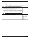
• Upgrading the MGCP Signaling Image, page 3-26—This section provides references to the various
means of upgrading your Cisco ATA signaling image.
Note The term Cisco ATA is used throughout this manual to refer to both the Cisco ATA 186 and the
Cisco ATA 188, unless differences between the Cisco ATA 186 and Cisco ATA 188 are explicitly stated.
Default Boot Load Behavior
Before configuring the Cisco ATA, you need to know how the default Cisco ATA boot load process
works. Once you understand this process, you will be able to configure the Cisco ATA by following the
instructions provided in this section and in the sections that follow.
All Cisco ATAs are shipped with a bootload signaling-protocol image. However, because this image is
not a fully functional signaling image, the image must be upgraded. The image is designed to be
automatically upgraded by a properly configured TFTP server. To configure the Cisco ATA to
automatically upgrade to the latest signaling image, see the “Upgrading the Signaling Image from a
TFTP Server” section on page 7-1.
In addition, the Cisco ATA obtains its configuration file during the bootload process.
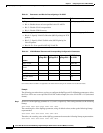
The following list summarizes the default Cisco ATA behavior during its boot-up process:
1. The Cisco ATA uses the Cisco Discovery Protocol (CDP) to discover which VLAN to enter. If the
Cisco ATA receives a VLAN ID response from the network switch, the Cisco ATA enters that VLAN
and adds 802.1Q VLAN tags to its IP packets. If the Cisco ATA does not receive a response with a
VLAN ID from the network switch, then the Cisco ATA assumes it is not operating in a VLAN
environment and does not perform VLAN tagging on its packets.
Note If your network environment is not set up to handle this default behavior, make the necessary
configuration changes by referring to the “Specifying a Preconfigured VLAN ID or Disabling
VLAN IP Encapsulation” section on page 3-3.
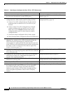
2. The Cisco ATA contacts the DHCP server to request its own IP address.
Note If your network environment does not contain a DHCP server, you need to statically configure
various IP addresses so that the Cisco ATA can obtain network connectivity. For a list of
parameters that you must configure to obtain network connectivity, see Table 3-6 on page 3-21.
For instructions on how to use the voice configuration menu, which you must use to perform this
configuration, see the “Voice Configuration Menu” section on page 3-20.