


Appendix E—Auxiliary Alert Option
Installation Instructions
APPLICATION
INFORMATION
HOW IT WORKS
INSTALLATION
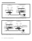
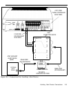
The following instructions utilize the WP91683 L1 Power
Supply for the AT&T Door Phone Controller external alert
feature.
The WP91683 L1 Power Supply is the interface
48VDC to operate external alert features for the
for providing
AT&T Door
Phone Controller such as bells, horns, lamps, strobes, and
chimes.
The WP91683 L1 Power Supply is a plug-in power supply
capable of providing 48VDC at up to 200 milliamps. The power
supply operates from a 115/120 volt AC standard single or
duplex receptacle.
The AT&T Door Phone, in conjunction with a telephone system,
provides a means to alert a customer that a doorbell button has
been pressed. In response the customer can answer and talk
to the door from a telephone within the customers premises.
The alerting device function can be provided by an external
alert device powered by the WP91683 L1 Power Supply. The
AT&T Door Phone’s AUX. ALERT contact closure is used by
the WP91683 L1 Power Supply to provide 48 Volts DC to
activate the external alert device.
These instructions apply to the use of a four-conductor modular
cord
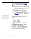
1.
2.
only.
Locate the WP91683 L1 Power Supply as close as pos-
sible to the AT&T Door Phone Controller (the nearest
wall receptacle, DO NOT PLUG IN YET).
Run a standard 2-pair wire DIW or equivalent between
the AT&T Door Phone Controller and a 103A connect-
ing block. Connect jack on the 103A block to the jack
Auxiliary Alert Device Connections E-1