


Introduction
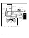
This section provides instructions for installing your AT&T Door
Phone Controller. Provided are installation instructions for an
Contact a licensed electrician
for installation of optional
devices such as an electric
strike plate and auxiliary alert
device which may require
electrical wiring. For the electric
strikeplate, a low voltage device
(24 volts or less) is
recommended.
optional electric door strike plate, door ajar contacts, and an
auxiliary alert device. These optional components must be
installed prior to the installation of your AT&T Door Phone
Controller. (Refer to the respective installation manuals for
specific mounting and wiring instructions.) The flow-chart
provided in Figure 2-9, will help direct you to the next
appropriate section for attaching the AT&T Door Phone
Controller to the telephone equipment in your home or
business (also see Compatibility Chart on page iii).
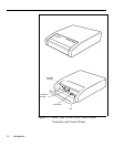
Inside the AT&T Door Phone Controller shipping carton
you will find:
■ The AT&T Door Phone Controller unit
■ Mounting template (along the edge of the Tear-out
Reference Card)
■ Power cord and attached transformer
■ Two mounting screws
■ Two 6-conductor modular-to-modular 6 foot long cables
■ Terminal strip connector
■ Instruction Manual (this manual)
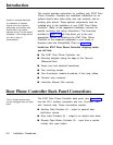
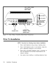
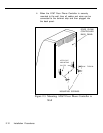
Door Phone Controller Back Panel Connections
The 14-contact terminal strip
The AT&T Door Phone Controller back panel (see Figure 2-1)
can be unplugged from the back
has two RJ11 modular connectors and one 14-contact “hard
panel.
wire” terminal strip. These connections provide:
■ Auxiliary Alert Contacts (2) – output to optional door
bell/chime device.
■ Door Latch Contacts (3) – output to an electric door strike.
■ Remote Open Button Contacts (2) – input from a remote
(inside) door open button.
2-6 Installation Procedures