


1 2 3 4 5 6 7 8
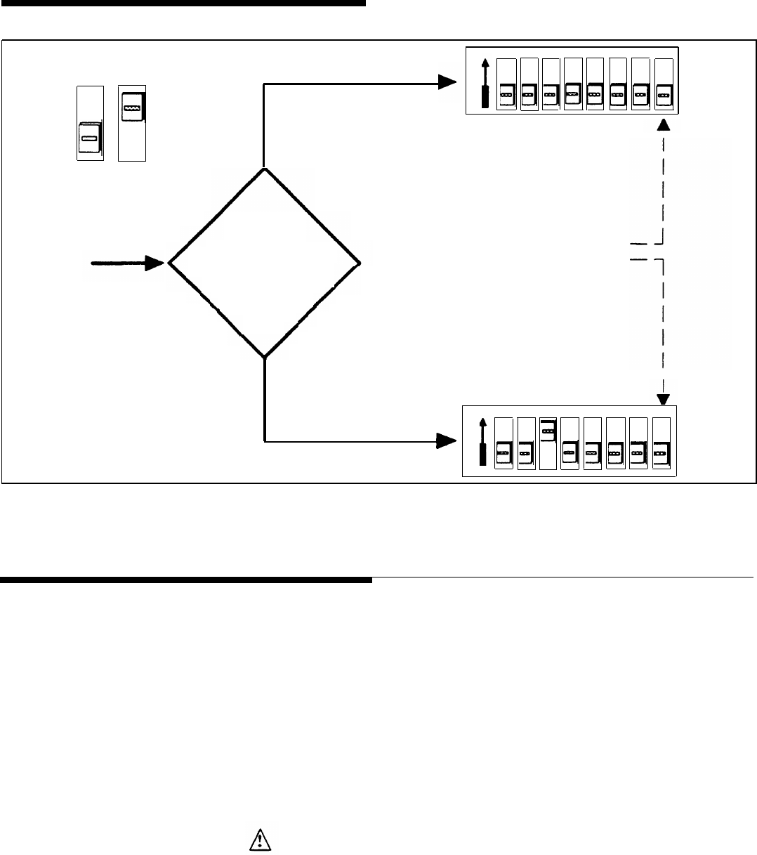
LEGEND
ON
Off On
LOOP START
.
. . The C.O.
(Trunk Saver Mode)
Immediately
after cut-thru
(Dialing Trunk) to AT&T
Door Phone Controller,
what do you want to
be connected
to...?
.
. . The DOOR
(Port Saver Mode)
1 2 3 4 5 6 7 8
ON
LOOP START
ON for
Option Selection
Mode Only
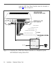
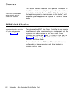
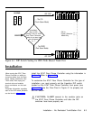
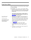
Figure 6-1. DIP Switch Setting for PBX With Shared Trunk Port
Installation
When moving the AT& T Door
Phone Controller or adding or
removing cables from the back
panel, unplug transformer from
120V outlet, Also unplug the
terminal strip and modular
phone connectors on the back
panel.
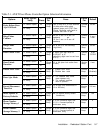
Complete information regarding
each of the DIP switch positions
can be found in Appendix A.
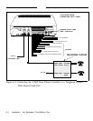
Install the AT&T Door Phone Controller using the information in
Section 2. Refer to Figure 6-2.
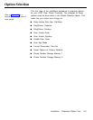
To customize the AT&T Door Phone Controller for this type of
installation, you must properly set the 8-position DIP switch
located on the AT&T Door Phone Controller front panel (see
Figure 1-1). Use the Flow Chart in Figure 6-1 to properly set
the DIP switch.
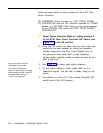
CAUTION: Do NOT connect to the modular jacks on
the AT&T Door Phone Controller until after the DIP
switches
have been
Installation
properly set.
- No Dedicated Trunk/Station Port 6-3