


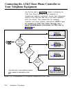

NOTE: One or the other will
apply, not both.
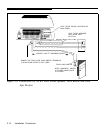
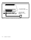
3. Verify all connections when connecting the door strike
contacts on the AT&T Door Phone Controller to existing
door open buttons. Make sure of the following:
■
■
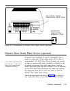
Auxiliary Alert Device
The NO and C contacts are connected in parallel to a
normally-open button.
The NC and C contacts are connected in series to a
normally-closed button.
(optional)
In most configurations, the Door Phone Controller will cause a
telephone to ring when the doorbell button is pushed. An aux-
iliary alert device (chime, bell, horn, tone generator, etc.) can
also be used as an alert to notify the person inside the building
that the doorbell button has been pushed (Auxiliary Alert
If the Auxiliary Alert Device has
Mode). A low-voltage device (24V or less) is recommended.
more than a 1 Amp draw, then
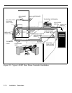
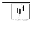
Follow the steps below (refer to Figure 2-7) for wiring auxiliary
an external relay arrangement
will be required.
alert device (door bell/chime) to the Door Phone Controller:
1.
Install the auxiliary alert device (door bell/chime) as in-
structed by the manufacturer’s installation manual.
See Appendix E for specific
2. The Normally Open (N.O.) and Common (C.) relay con-
auxiliary alert device installation
tact, located on the Door Phone Controller back panel
information.
(see Figure 2-7), are accessible at the Door Phone Con-
troller terminal block. Wire these to the auxiliary alert
device and it’s power source as instructed by the
manufacturer’s installation manual.
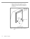
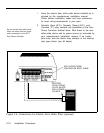
Connecting Power
When the Door Phone Controller has been mounted to a wall
or placed on a shelf and all cables and wires have been
connected to the back panel, plug the transformer into a 120
VAC outlet. See Figure 2-8.
Installation Procedures 2-17