


SpectraLink Corporation Installation and Operation
Link WTS – Link 150 M3 MCU
3. Link Wireless Telephone System Overview
Review this section if you are unfamiliar with the features and operation of the Link
WTS.
3.1 System Operation
The Link WTS is a wireless communication system that offers direct telephone
access for incoming and outgoing calls anywhere within a facility.
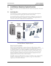
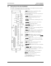
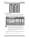
The Link WTS consists of three basic components: the Master Control Unit, the
Base Station and Link Wireless Telephones, or handsets. This diagram shows an
overview of the system. Components are described below.
M
aste
r
Control
U
ni
t
Link
Wireless
Telephones
B
ase
Stations
Analog or
Digital
Interface
PBX
Application
Server
OAI
Gateway
The Link Wireless Telephone System
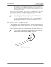
Master Control Unit (MCU)
Serves as the connecting point, or gateway, between the Base Stations and the
existing telephone system. One or more of these boxes (approximately 12” x 3” x 7”)
are typically installed in the telephone equipment room and provide connectivity
from the telephone system to the Link WTS. Each MCU is hard-wired to one or
more Base Stations, which in turn provides the wireless link to each of the Link
handsets. The MCU establishes the connection from the telephone line to the
appropriate Base Station in order to reach a handset.
The MCU supports four Base Stations and up to 16 handsets. Up to four Link 150
M3 MCUs can be linked together for extended coverage area. Chained MCUs
support up to 64 handsets maximum.
PN: 72-0075-01-F.doc Page 9