


SpectraLink Corporation Installation and Operation
Link WTS – Link 150 M3 MCU
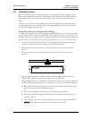
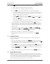
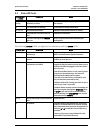
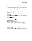
9.3 Status LED Codes
STATUS LEDs
1 2 3 4 5
Description Action
Random
Cycling
The Link 150 M3 MCU is powering up.
Initialization to follow.
This is not an error and should change to another code
after a minute.
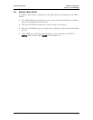
5 Link 150 M3 MCU is initalizing. Code number will change when finished.
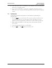
1, 2, 3, or 4 MCU identification number. Indicates normal operation when it is on steady.
If the same LED is lit on more than one
MCU:
Check the IPC connections.
If the LED is flashing and the ERROR
light is on:
There is a problem with the MCU indicated by the
flashing box ID.
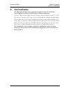
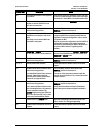
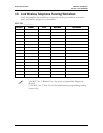
The following
STATUS LEDs are displayed in combination with the ERROR LED.
STATUS LEDs Description Action
1, 2, 3, 4, 5 MCU has not been configured for switch
interface type.
Assign a switch type to the MCU. See section 6.3
Install
MCUs -Set Switch Interface T pe
for instructions.
y
1, 3 A Base Station has reported an internal
problem.
Replace the Base Station. In rare cases a problem with
the MCU can cause this error.
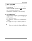
2, 3 No communication with one or more
Base Stations on this MCU.
Check cabling to verify that the Base Station’s cable is
plugged into and fully seated in the Base Station port at
the back of the MCU and plugged into the Base Station
at the other end.
If the LED on the Base Station is not lit, check for proper
wiring of the 8-pin modular plugs. See section 5.3
Terminate Cable at Base Station Locations
.
If the cable is over 600 feet long, verify that the extra
wire pairs have been connected correctly.
If the
Base Station LED is flashing red, check for open or
shorts on pins 1 and 2 of the cable.
If the Base Station has been removed, acknowledge the
alarm by moving the mode switch to
REGISTER. Press
the
STEP button until the LED for the removed Base
Station is blinking. Press
DEL/ENTER, then move the
mode switch back to
NORMAL.
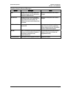
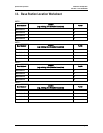
1, 2, 3 Internal communication problem with the
MCU.
Replace the MCU.
4 IPC problem. Check IPC cabling by disconnecting and reconnecting
the MCUs. Connect the Male RJ-21 connector from the
appropriate demarcation block to the designated RJ-21
connector (
A or B) on each MCU. Secure cables using
the keeper.
If the error still occurs try using a different IPC cable.
Replace MCU if the problem still occurs.
PN: 72-0075-01-F.doc Page 36