


SpectraLink Corporation Installation and Operation
Link WTS – Link 150 M3 MCU
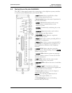
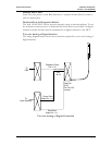
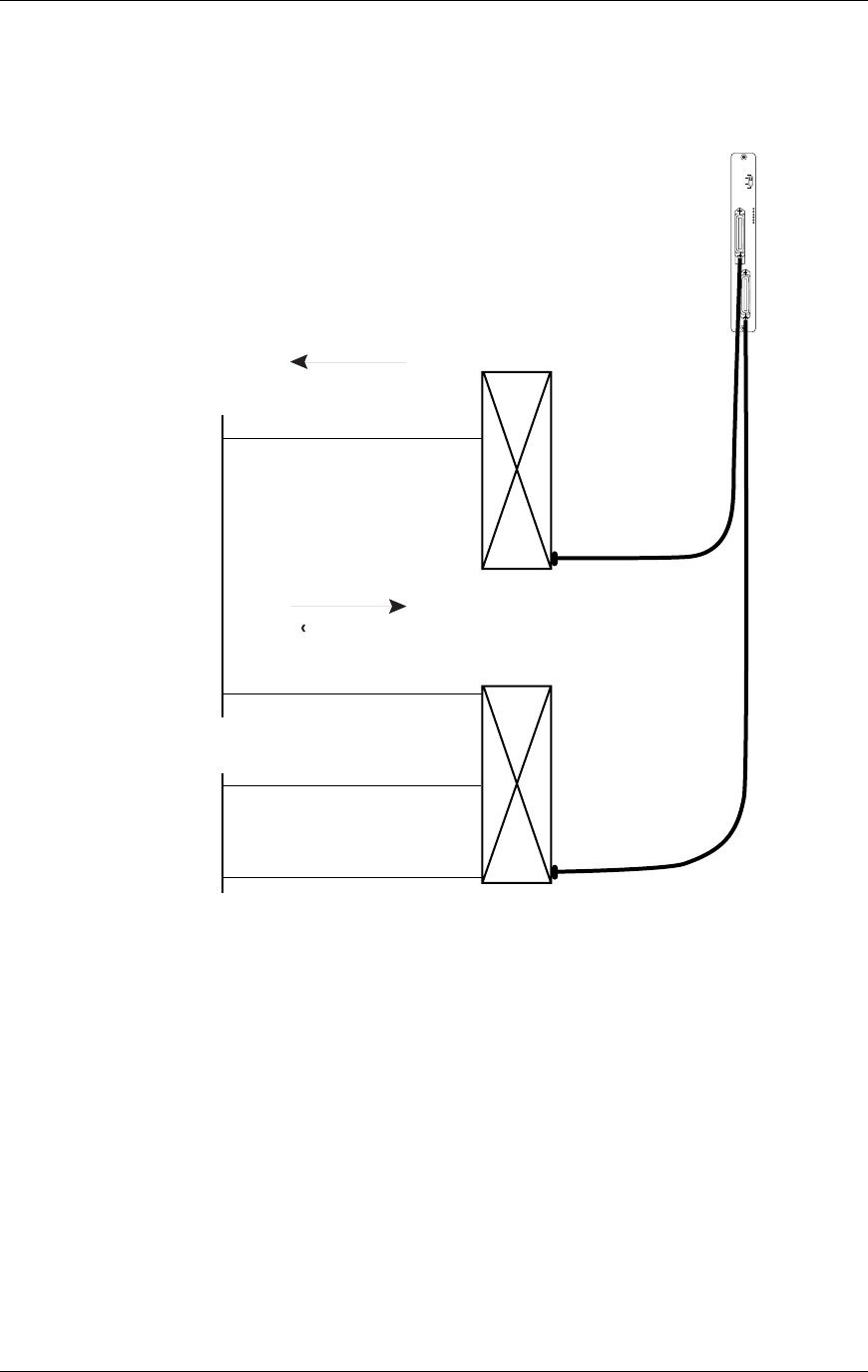
Four-wire Digital Interface
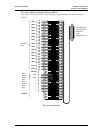
The wiring diagram below shows the connections required for a four-wire interface .
Each MCU of this type requires two demarcation blocks which will be wired as
indicated.
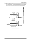
A
B
Receive (RX)
To PBX
Telephone Ports
Pair 1-16
Pair 17-25 Unused
Transmit (TX)
From PBX
Telephone Ports
Pair 1-16
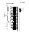
Power Pairs 18-19
Base Stn. 1-4
Data Pairs 20-23
Base Stn.1-4
Pair 24 & 25 Unused
To
PBX
To
Base Stations
Pair 17 - Unused
Four-wire Digital Connection
PN: 72-0075-01-F.doc Page 17