


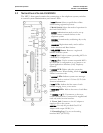

SpectraLink Corporation Installation and Operation
Link WTS – Link 150 M3 MCU
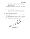
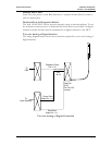
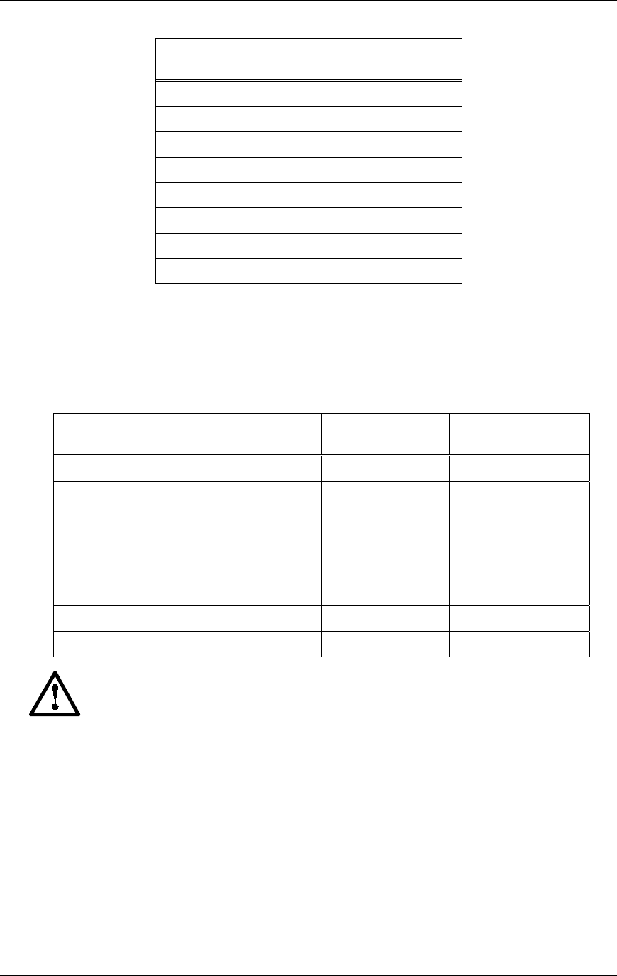
When wiring the 8-pin connector, use the following table as a guide.
8-pin Modular
Connector
MCU Pin
Function
Polarity
1 Data 1 Any
2 Data 2 Any
3 Power 3 +
4 Power 2 -
5 Power 2 +
6 Power 3 -
7 Power 1 -
8 Power 1 +
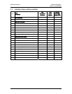
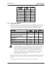
5.4 Prepare Demarc Blocks
The MCU connects to the existing telephone system using RJ-21 connections. An
MCU is designed to operate with a specific interface to the telephone system: two-
wire digital or analog, or four-wire digital. The number of demarcation blocks
required for the system depends on the number and type of MCUs installed.
Interface Type
MCU
Part Number
Wire
Pairs
# Blocks
Analog POTS SCA-5XX 1 1
Universal Digital Interface
(Norstar, Meridian, Comdial, Fujitsu, Inter-Tel,
DEFINITY 2-wire, NEC, Rolm, Toshiba)
SCU-5XX 1 1
Merlin Legend and
DEFINITY 4-wire
SCF-5XX 2 2
Mitel (DNIC) SCX-5XX 1 1
Panasonic (Universal 2-wire Auxiliary Digital) SCP-5XX 1 1
Executone (Universal 4-wire Auxiliary Digital) SCB-5XX 2 2
If the wiring between the Link 150 M3 MCU and the telephone system
leaves the building, consult your telephone system manual for instructions
on providing adequate lightning and other over-current protection. All
MCUs (except the analog interface SCA-5XX) are intended only for
connection to the isolated side of an on-premises telephone switch. The
interfaces are intended to connect to digital telephone switch ports that
provide signals of 5Vp-p (max) AC component, and some telephone
switches provide a 48 V DC offset.
Based on the number and type of interfaces in the system, determine the number of
25-pair cables required to connect line ports and Base Stations to the demarcation
blocks.
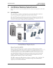
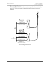
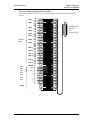
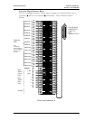
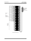
The diagrams which follow provide an overview of the connections.
PN: 72-0075-01-F.doc Page 15