


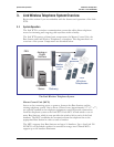


SpectraLink Corporation Installation and Operation
Link WTS – Link 150 M3 MCU
4. Site Preparation
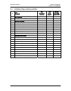
4.1 Required Materials
The following equipment must be provided by the customer:
Outlet Strip Recommended for installations with more than one MCU. This
will allow the MCUs to be turned on and off together.
Cross-Connect Block Required to connect the telephone switch ports and the
Base Stations to the MCU.
25 Pair Cables RJ-21 male at MCU end, required to connect the MCU to the
cross-connect blocks.
Backboard Space The MCU is designed to be wall mounted to 3/4” plywood
securely screwed to the wall.
Quick Clip Fuse Required with an RCO410 Outdoor Base Station or when a
Base Station is located in a separate building from the Link 150 M3 MCU.
Recommended Quick Clip Fuse is available from Illinois Tool Works, Linx
Division, Model # SCP-2X2.
Base Station Mounting Hardware If the Base Stations will be mounted on
finished walls or ceilings, a 4 to 5” long 1/4” bolt, nuts, and washers will be
required for each Base Station mounted.
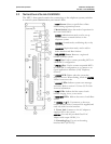
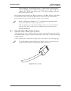
4.2 Determine Location of MCU
Each MCU is approximately 2.75” wide, 12.5” high, and 7” deep, and weighs about 5
pounds. The unit is designed to be wall-mounted over 3/4” plywood.
• Select a location for the MCU with sufficient backboard space and an available
outlet.
• The MCU must be within 2,200 feet of the Base Stations.
• All digital interface modules must be within 250 feet of the telephone system.
• See your telephone system specifications for distance limitations for analog
modules.
• Since the front panel is used for cabling and as an operator’s console, mount the
units so the front panel is accessible.
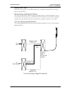
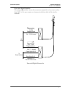
If your system has more than one MCU, the units should be mounted
vertically, side by side, physically touching the adjacent unit. Do not stack
units on top of one another. Stacked MCUs can cause overheating and
failure.
PN: 72-0075-01-F.doc Page 12