


SpectraLink Corporation Installation and Operation
Link WTS – Link 150 M3 MCU
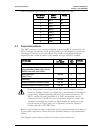
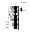
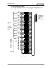
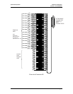
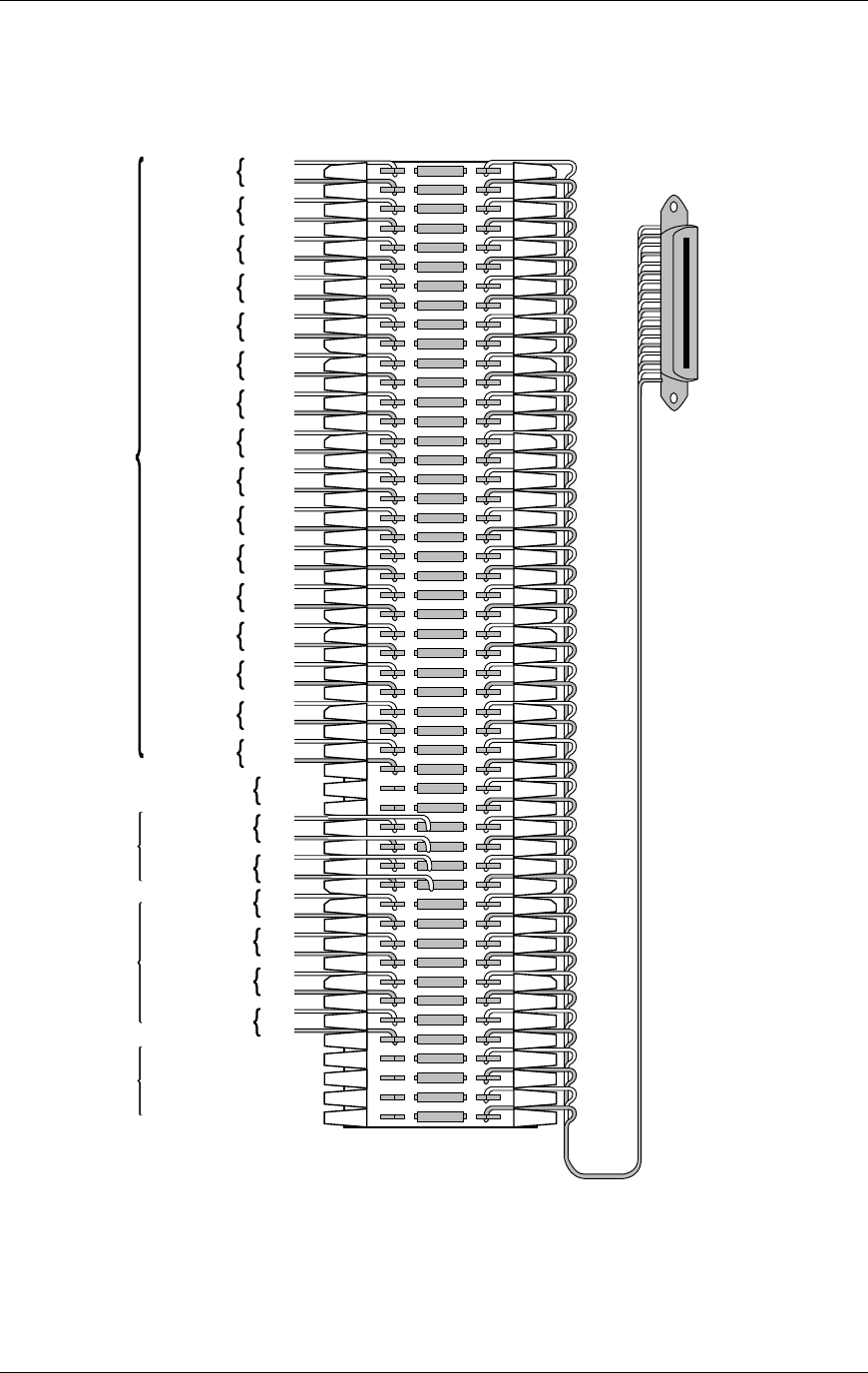
Four-wire Digital Demarc Block
The four-wire digital interface (future release) requires two demarc blocks, one to
Connector A and one to Connector B on the MCU. They should be wired as
follows.
Line 1 TX
tip
ring
Line 2 TX
tip
ring
Line 3 TX
tip
ring
Line 4 TX
tip
ring
Line 5 TX
tip
ring
Line 6 TX
tip
ring
Line7 TX
tip
ring
Line 8 TX
tip
ring
Line 9 TX
tip
ring
tip
ring
tip
ring
tip
ring
Line 13 TX
tip
ring
Line 14 TX
tip
ring
Line 15 TX
tip
ring
Line 16 TX
tip
ring
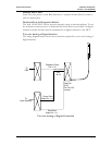
25 PAIR MALE
CONNECTOR
CABLE TO
MCU
CONNECTOR A
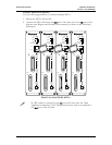
Telephone
Ports
UNUSED
1, & 2
3 & 4
1
2
3
4
Base
Station
Power
Pairs
Base
Station
Data
Pairs
Line 10 TX
Line 11 TX
Line 12 TX
Note:
TX denotes
data transmitted
from the telephone
system to the
Link150
Unused
Four-wire Connector A
PN: 72-0075-01-F.doc Page 21