


SpectraLink Corporation Installation and Operation
Link WTS – Link 150 M3 MCU
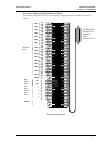
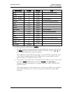
Switch Interface Line LEDs MCU Type Notes
Analog 1 SCA5xx The SCA will only support Analog.
Comdial 3 SCU5xx
DEFINITY – Two-wire 1, 4 SCU5xx
DEFINITY – Four-wire 1, 5 SCF5xx Four-wire Interface.
Executone 2, 5 SCB5xx The SCB will only support Executone.
Fujitsu 2, 4 SCU5xx
Inter-Tel 2, 3, 4 SCU5xx
Meridian 1, 2 SCU5xx
Merlin Legend 1, 3 SCF5xx Four-wire Interface.
Mitel 1, 2, 3 SCX5xx The SCX will only support Mitel.
NEC 1, 2, 4 SCU5xx
Norstar 2 SCU5xx
Panasonic 5 SCP5xx The SCX will only support Panasonic.
Siemens / Rolm 4 SCU5xx
Toshiba 2, 3 SCU5xx
Unconfigured 1 through 8
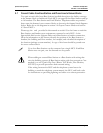
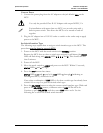
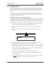
6. Move the mode switch back to NORMAL.
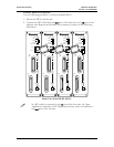
7. The MCU will cycle through diagnostic testing. When the system is ready for use,
the ERROR LED should be off, and the LED for the MCU Number (1 to 4) will
be lit. This should take less than two minutes.
If the LED for the MCU ID does not light, or if an MCU ID is duplicated, there
is most likely a problem with the IPC cabling. If the system displays an error
refer to section 9.1
Troubleshoot Error Codes
.
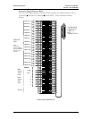
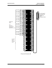
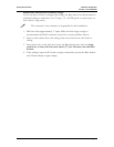
8. If you select a switch type that is not supported by the MCU type, the system will
alarm. The
ERROR LED will flash along with STATUS LEDs 4 and 5. For
example, this alarm will display if you assign switch type NEC to an SCB-5XX –
Executone MCU.
If this alarm displays, use the table above to verify that your MCU type supports
the selected switch type. If you need to change the switch type, repeat steps 2
through 6.
PN: 72-0075-01-F.doc Page 27