


SpectraLink Corporation Installation and Operation
Link WTS – Link 150 M3 MCU
Index
AC Adapter, 23
A-law, 45
Alternate sequence, 44
Attenuation, 13
Base Station, 23
Cabling, 13, 14
Description, 10
Installation, 28
LED, 35
Location form, 43
Outdoor, 30
Outside Wiring, 30
Replacing, 41
Battery Chargers, 24
Cabling
Base Station specifications, 13
Base Station, external, 18
Base Station, internal, 13
Demarcation blocks, 18
Exiting the building, 14
Four-wire digital, 17
IPC, 27
Prepare Demarc Blocks, 15
Quick Clip Fuse, 12
RJ-45 modular, 14
Shipped with system, 23
Troubleshooting, 36
Two-wire analog or digital, 16
Ceiling clip, 23, 28
Chargers, 24
Companding, 45
Configuration sharing, 40
Connecting MCU to Telephone System, 15
Coverage, 10
Customer Support Hotline, 6
Demarcation blocks
Four-wire digital, 21
Installing, 18
Two-wire analog or digital, 20
Diagnostic Modem, 16
Error Codes, 35
ESD bonding strap, 24
Extension numbers, 39
Batteries, 24
Forms
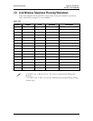
Base Station location, 43
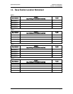
Wireless Telephone
Planning Worksheet, 42
Frequency, transmission, 44
Hand-off, 10
Hotline, 6
Interface types, Demarc, 15
Interference, frequency, 44
LED
Base Station, 35
Codes, 36
Front Panel, 11
Line indicator, 11
Troubleshooting, 35
Link WTS, Overview, 9
Master Control Unit. See MCU
MCU
Base Station cabling, 13
Connect to Demarc Blocks, 25
Description, 9
Front Panel, 11
Location, 12
Mounting, 24
Multiple, 25
Replacing, 40
Mode Switch, 11
Modem, 16, 31
Mounting Hardware, 23
Mu-law, 45
PBX type, 26
Power
AC Adapter. See
Outlet strip, 12
Power jack, 11
Programming, 18
Quick Clip Fuse, 12
Register Wireless Telephone, 31
Remote Access via modem, 16
Replacing
Base Station, 41
MCU, 40
Wireless Telephone, 39
PN: 72-0075-01-F.doc Page 46