


SpectraLink Corporation Installation and Operation
Link WTS – Link 150 M3 MCU
Multiple Power Pairs
Some sites may prefer to wire Base Stations to a separate demarc block in order to
split out power pairs.
Dedicated Line for Diagnostic Modem
The Link 150 M3 MCU can be accessed remotely using an internal modem. To use
the modem for remote access, a dedicated dial-in line must be provided. On digital
interface systems this line must be terminated as a digital extension to the MCU.
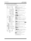
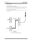
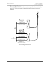
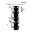
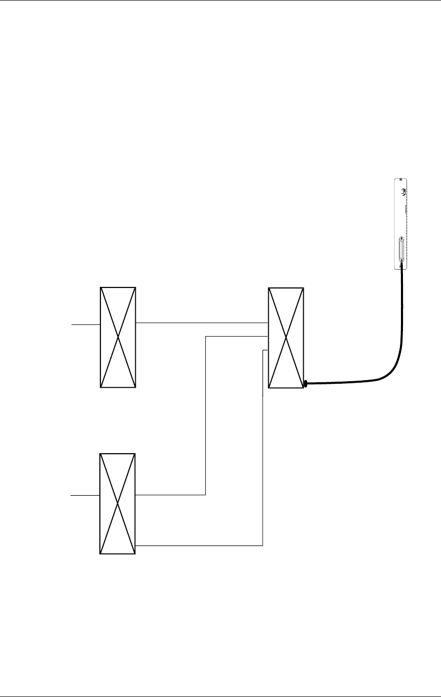
Two-wire Analog or Digital Interface
The wiring diagram below shows the connections required for a two-wire analog or
digital interface.
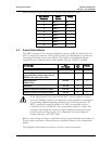
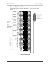
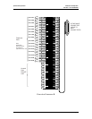
Telephone Ports
Pair 1-16
Pair
18-19
Data Pair
20-23
Pair 24 & 25
Unused
Power Pairs
Base Stn. 1-4
Data Pairs
Base Stn. 1-4
To
Base Stations
To
PBX
A
Pair 17 Unused
Two-wire Analog or Digital Connection
PN: 72-0075-01-F.doc Page 16