


RTU-292 Operations Manual
6 Maintenance and Repair
6.1 GENERAL
Included in this section are the Test Procedures and performance evaluation criteria for the
supplied equipment. Also provided is a Fault Analysis Table (Table 6.1) to aid in isolating a
fault. Table 6.2 identifies replaceable parts.
6.2 PREVENTIVE MAINTENANCE
There are no preventive or periodic maintenance requirements for this equipment.
6.3 REPAIR OR REPLACEMENT
The repair or replacement of damaged and/or defective parts generally requires techniques that
are standard in the industry. Carefully examine the equipment to determine the most correct
and least time-consuming method required to make the repair.
6.3.1 GENERAL PRECAUTIONS AND NOTES
1. Disconnect power from the unit before attempting any repair or replacement of components.
2. Replace defective connectors only with identical items.
3. Carefully observe lead dress and component orientation when repairing circuits. Keep
components leads as short as possible.
4. Reference to the component side of a printed circuit board denotes the side of the board on
which the components are mounted. The solder or circuit side refers to the side opposite the
components.
6.4 ALIGNMENT
No alignment is required or possible other than setting levels for the telephone line, receiver
input and transmitter output which are done as a part of the normal equipment setup procedure.
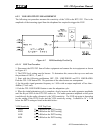
6.5 PERFORMANCE TESTING
This section describes how to test and verify the basic performance of the RTU-292. Extensive
test procedures pin-pointing the location of internal faults to the component level are beyond
the scope of this manual.
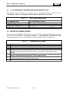
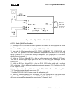
6.5.1 TEST EQUIPMENT REQUIRED
1 ea. Audio Signal Generator, 600 Ohm Output
1 ea. Noise Generator or Radio Receiver
(See NOTE below)
1 ea. Audio Voltmeter, Hi-Z Input
(HP 400H or equivalent)
1 ea. Resistor, 560 Ohm to 680 Ohm, 1/4W min
JPS Communications, Inc.
6-19