


RTU-292 Operations Manual
7.4 VMM-100 OPTION
The VMM-100 VMR Module implements Voice Modulation Recognition (VMR) which
enables the receive audio path when speech is present and disables it when speech is not
present. This module also implements a form of noise reduction known as "dynamic peaking"
which reduces background white noise. These features are implemented with a DSP circuit on
the VMM board.
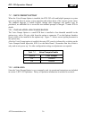
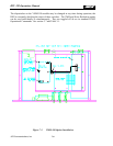
7.4.1 VMM-100 Hardware
The general purpose of the DSP hardware is to convert analog audio signals to the digital
domain, operate on and manipulate these signals digitally, then convert the result back to
analog.
7.4.1.1 VMM-100 DSP Section
The heart of the DSP section is the DSP chip itself, a TMS320C25. The unit runs at 40 MHz
and produces a 5 MHz signal at the U1-58 CLKOUT, which supplies timing to PEEL U3 and
ultimately to U2, the Analog Interface Chip. U2 then supplies an interrupt to the 320C25
approximately every 130 microseconds, which establishes the sample rate of about 8 kHz. The
DSP operating program is contained in EPROM chips U5 and U6. Two chips provide the
necessary 16-bit-wide architecture; the high byte is contained in U5 and the low byte in U6.
Static RAM chips U9 and U10 are used for temporary data storage during operation of the
program.
All of the "glue" logic necessary to interface the DSP with the various peripheral chips on the
board is provided by PEEL (Programmable Electrically Erasable Logic) U3.
U8 is a reset generator that insures an orderly power-up sequence for the DSP and associated
components. It senses the voltage on the +5V line and generates a reset while the voltage is
below approximately 4.55V. As the voltage rises above the threshold, a delay is generated by
C8 to insure processor clock stability before operation commences. Resistor R2 prevents U8
from resetting on short spikes on the 5V line.
Latch U4 provides an eight-bit parallel output from the DSP. Two of the outputs are used
(NR3 and NR4), while the other six are spare. Latch U12 provides an eight-bit parallel input to
the DSP. Two of the inputs are used (NR1 and NR2), while the other six are spare. Latch U11
provides a means for the DSP to read SW1 switch settings.
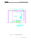
7.4.1.2 VMM-100 Analog Interface
Chip U2 provides the analog interface to the DSP section. This chip is type TLC32040 and
contains an A/D converter for the analog input, D/A converter for analog output, and an anti-
alias filter before the A/D, and a reconstruction filter after the D/A. The chip derives its own
timing for these functions from the master clock provided by the DSP. These chips are
interfaced to the DSP via a serial bus.
Amplifier U13 is a dual op-amp that provides gain-of-one buffer amplifiers for the analog
audio input and output.
JPS Communications, Inc.
7-6