


RTU-292 Operations Manual
and +28 VDC (nominal) supplies. The unit will automatically switch over to the use of the DC
input when the AC source drops too low or is not available. Slide switch S6 on the Main Board
is used to select either +12 or +24/+28 VDC operation. S1 is located near the left front edge of
the Main Board; the +12V and +24/+28V switch positions are clearly marked on the board.
The RTU-292 is set in the factory to the +24/+28 VDC position.
2.8 CONFIGURING THE RTU-292
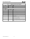
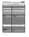
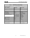
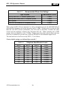
The RTU-292 factory default settings are listed in Table 2-1. The factory set-up will be correct
for most installations; explanations of each feature selection method or other adjustment are
provided for systems requiring different set-ups. If any setting must be changed, refer to Figure
2-3, “Internal Adjustments Locations”. Remove the top cover of the unit by removing the
Phillips-head screws around its edges.
NOTE:
Many of the RTU-292's operating parameters are set by internal eight-position
dipswitches SW1 and SW2. These switches are read by the RTU-292
microprocessor only when the unit power is turned on. To change any dipswitch
controlled parameter, turn off the RTU-292, change the switch setting(s), and then
turn the unit power back on.
2.8.1 PROGRAMMING MODE SETUP PARAMETERS
Some of the RTU-292 setup options are selected by entering DTMF commands by a connected
telephone or Local Phone Option telephone set. Since these parameters are set after a
connection is made, they are detailed in section 3. See Table 3-2, “Programming Mode DTMF
Commands”.
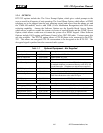
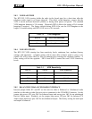
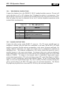
2.8.2 SETTING TELEPHONE SEND AND RECEIVE LEVELS
The levels of the audio signal that are sent into (Send) and received from (Receive) the
telephone line are adjustable via SW2 switches 1 through 3 on the RTU-292 Main Board. The
levels are adjustable from -21 dBm (600 Ohm) to 0 dBm in 3 dB steps. The dipswitches
simultaneously set the Send and Receive levels.
JPS Communications, Inc.
2-5