


RTU-292 Operations Manual
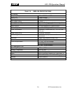
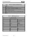
Table 7-7 VMM-100 I/O CONNECTOR INFORMATION (P9)
Pin Signal
1 Audio Input (see specs above)
2 Audio Output (see specs above)
3 NR1; Logic Input; Low selects DSP Noise Reduction
4 NR2; Logic Input; Low selects DSP Voice Modulation Recognition
5 -5V; Supply Input (see specs above)
6 +5V; Supply Input (see specs above)
7 +12V; Supply Input (see specs above)
8 NR3; Logic Output; Follows state of SW1-1; Low indicates default is NR on
9 NR4; Logic Output; Follows state of SW1-2; Low indicates default is VMR on
10 Ground
Table 7-8 VMM-100 Switch Functions
SW1-1 FUNCTIONS
SW1-1,2 For future use; leave off
SW1-3, 4 FUNCTIONS
SW1-3 SW1-4 Threshold
On On 1 (lowest)
Off On 2 Factory Default
On Off 3
Off Off 4 (highest)
SW1-5, 6 FUNCTIONS
SW1-5 SW1-6 Hangtime
On On 0.75 seconds
Off On 1.25 Factory Default
On Off 1.75
Off Off 2.25
SW1-7, 8 FUNCTIONS
SW1-7 SW1-8 Delay
On On 0 msec
Off On 100 Factory Default
On Off 200
Off Off 300
JPS Communications, Inc.
7-10