


RTU-292 Operations Manual
8 SCHEMATIC DIAGRAMS
8.1 GENERAL
This section has all RTU-292 schematic diagrams. They include:
Figure 8-1 Front Panel Schematic
A single sheet showing the switch boards and other front panel components.
Figure 8-2 Main Board Schematic
This nine page schematic details all components on the main board. Notes are included to
differentiate the schematic when the board used in different JPS products, the RTU-292, the
RTU-300 (desktop version), and the RTU-285 (special application version- not for general
sale). There are two different power supply schematics. On the eighth page is the schematic
for the power supply configuration used with the RTU-292 or RTU-300. The ninth page is the
power supply configuration for the RTU-285 only.
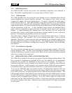
Figure 8-3 DSP Module
The DSP Module that plugs into the Main Board via a pair of in-line 20-pin headers has two
schematic pages.
Figure 8-4 Option Interface Board
This is a single-sheet schematic for the narrow PCB that resides in the side of the options tray
and provides an interface between the various standard option boars and the main PCB.
Figure 8-5 Voice Prompt Option Board
Figure 8-6 Local Phone Option Board
Figure 8-7 VMM-100 Option Board
JPS Communications, Inc.
8-1