


RTU-292 Operations Manual
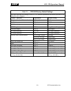
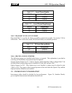
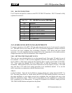
Table 2-12 Local Phone Enable
SW1-7 Local Phone
Off Disabled
On Enabled
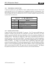
Table 2-13 Local Phone Ringthrough
SW1-8 Ringthrough
Off Disabled *
On Enabled
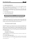
2.8.15 TRANSMIT LEVEL SET-UP MODE
Dipswitch SW2-7 is used by the factory to enable a special set-up mode. See section 2.10 for
instructions. This switch must remain Off (Normal Mode) for standard operation.
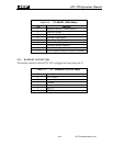
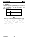
Table 2-14 TX Level Set-up Mode
SW2-7 Set-up Mode
Off Disabled *
On Enabled
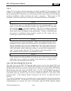
2.8.16 MISCELLANEOUS JUMPERS
The following jumpers are installed in the factory as required. This explanation is provided in
case they are accidentally removed and must be replaced.
Security Option Jumpers on J5. Unless a Security Option Interface Cable is plugged into J5 on
the Main Board, jumper plugs must be installed at J5 pins 4&5 and pins 7&8.
Option Jumpers on J10. If the Option tray is not installed, a jumper must be placed at pins
13&14 of J10. This jumper allows normal operation of the unit when the Options Tray and the
Options Interface Board are not installed.
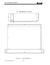
2.9 INTERCONNECT INFORMATION
Interconnect cables should be shielded for best performance. Figure 2.6, Interface Details,
gives simplified interconnect information about the unit.
JPS Communications, Inc.
2-11