


RTU-292 Operations Manual
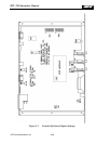
3.3 REAR PANEL CONNECTORS
Accessible at the RTU-292 rear panel are the radio connector, telephone line and local phone
connector, the signal terminal block, the DC power terminal block, an RS-232 connector, and
the AC power connector/voltage selector/fuse holder assembly. See section 2.9 for full pin-out
information.
3.3.1 P1 RADIO CONNECTOR
This male DB9 connector is the interface between a radio system and the RTU-292. It contains
transmit audio, receive audio, and keylines.
3.3.2 J1 TEL LINE
The RJ11C jack provides the telephone line connection to the RTU-292. The telephone line
connections are also available at the terminal block.
3.3.3 TERMINAL BLOCK
The terminal block is provided mainly as a convenience for the connection of the telephone line
to the unit if an RJ-11C plug is not available. This block also contains the key relay contacts to
the transmitter, remote key input signal, ground, and a spare External Signal Input.
3.3.4 J2 LOCAL PHONE CONNECTOR
This RJ-11C jack is used to connect a local phone to the unit. The Local Phone Option must be
installed for this port to be active.
3.3.5 P2 RS-232 CONNECTOR
This female DB-9 connector provides an interface between the RTU-292 and a radio or a
controlling terminal via standard RS-232 signal lines.
3.3.6 DC INPUT TERMINAL BLOCK
This two-position terminal strip has a pair of screw terminals, one for a ground wire and
another for the DC input of either +12 or +24/+28VDC (nominal). Internal slide switch S6 is
used to select between +12 and +24/+28 volt input. Refer to section 2.7.
3.3.7 P1 AC POWER CONNECTOR
This is a combination AC power connector, fuse holder and line voltage selector. It
incorporates a line filter to reduce the possibility of RF pickup by the power line from close-
proximity transmitters. Section 2.7 has complete instructions for the line voltage selection and
fuse replacement.
JPS Communications, Inc.
3-4