


RTU-292 Operations Manual
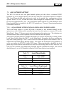
7.4.2 VMM-100 Software
The VMM-100 DSP software can provide voice modulation recognition, noise reduction, or
both. The module's operating mode is set by logic inputs at P9 pins 3 and 4
7.4.2.1 VMR Algorithm
The VMR algorithm works by passing the audio through a series of bandpass filters that are
spaced throughout the speech frequency spectrum. The outputs of these filters are then
examined for signals with speech characteristics. If speech is detected, the audio path is
enabled and the LED is lit. The VMR threshold is set by SW1 switches 3 & 4. This threshold
is not volume related; it specifies how stringent the VMR algorithm is when deciding whether a
signal contains speech. The correct setting will depend on many aspects of the incoming signal
and the requirements of the user. A lower threshold setting increases the likelihood that a
signal, which is comparable to speech, but does not actually contain speech, will be passed
through. A higher threshold will eliminate these false detections, but will increase the
possibility that a signal, which contains speech that is strongly masked by noise, will not be
detected.. The default setting should be good for most signals.
The audio output is delayed, allowing speech to be detected before audio arrives, so that no
syllables are missed. SW1 switches 7 & 8 set the duration of the delay. There is also an
adjustable "Hang-Time", which keeps the audio path enabled for an adjustable length of time
after the instant when speech is no longer detected. This hang-time prevents the disabling of
the audio path between syllables or during pauses in speech. SW1 switches 5 & 6 set the hang-
time duration.
7.4.2.2 Noise Reduction Algorithm
The noise reduction algorithm operates by passing the audio through an adaptive FIR (Finite
Impulse Response) filter. The filter forms instantaneous bandpass filters around the relatively
correlated information contained in speech, these filters are not created around non-correlated
white noise, causing it to be suppressed.
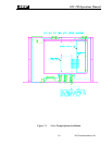
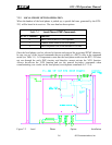
7.4.3 VMM-100 INSTALLATION AND CONFIGURATION
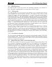
The VMM-100 is installed in the options tray opposite from the Options Interface Board. The
holes required for installation are included on the tray, but standoffs are not permanently
installed as this precludes the installation of other options at this location. See Figure 7-3.
Install the board with 6 screws, standoffs, lock washers, and nuts. Install the screws from the
bottom side of the tray. A cable tie-down is also supplied, and the VMM-100 option connector
is assembled to the 10 pin Noise Reduction Connector, J5, on the Options Interface Board.
To set up the VMM-100, place the separate switches of eight-position dipswitch SW1 per
system requirements. The LED on the board can be used to easily set the correct receive audio
level, which is necessary for optimal operation of the VMR and Noise Reduction Modes. This
LED normally indicates when speech has been detected, but when the VMR function is turned
off, this LED becomes a signal level indicator, and will flash on voice peaks when the correct
volume of speech containing signal is present. To use this LED to adjust the volume of the
audio input, turn the VMR function off (see Table 3-1) and inject speech at a normal speaking
level into the module's audio input. Adjust the input volume until the LED lights occasionally
on voice peaks.
JPS Communications, Inc.
7-7