


RTU-292 Operations Manual
2.9.1 TELEPHONE CONNECTION
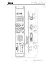
Connect the telephone line to the PHONE J1 RJ11C standard modular connector. The unit will
work with either an AC or DC telephone line. Telephone line polarity is not important. Note
that the phone connections are repeated at the terminal block on the rear panel for convenience.
Only one phone line may be connected; do not use J1 and the telephone connections on the
terminal block simultaneously.
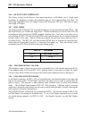
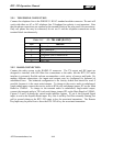
Table 2-15 J1 - TEL LINE (RJ-11C)
Pin Function
1 Not used
2 No Connection
3 Telephone Line Connection A
4 Telephone Line Connection B
5 No Connection
6 Not Used
2.9.2 RADIO CONNECTION
Connect the radio system to the RADIO J2 connector. The TX output and RX input are
designed to interface with 600 Ohm line connections at the radio, but the RTU-292 audio
interface is extremely flexible and can accommodate a wide variety of sources and loads. By
making different connections, the inputs and outputs may be configured for balanced or
unbalanced lines. The balanced configuration is the factory default and should be used if
possible, because it is the most noise-immune. To change to the receive audio to unbalanced,
single-ended input, connect the receive audio to RXA only and change jumper JP1 on the Main
Board to UNBAL. To change to the transmit audio to unbalanced, single-ended output,
connect the transmit audio to TXA only and change jumper JP3 on the Main Board to UNBAL.
Figures 2-5 and 2-6 details the various audio interface options. P1 pin 4, the External Signal
input, is used as the Squelch Break input. Key Out A and Key Out B are normally floating, but
pull to ground whenever the RTU-292 wants to key the associated transmitter. The Remote
Key Input may be pulled low to force the RTU-292 to key the associated transmitter.
JPS Communications, Inc.
2-12