


RTU-292 Operations Manual
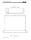
2.9.4 TERMINAL BLOCK
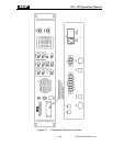
The terminal block on the rear panel is supplied for convenience when interfacing the RTU-292
to a communications system. The terminal block connections are in parallel with the I/O
terminals of the same name found on different connectors. If the telephone line connections at
Pin 1 and 2 of the terminal block are used to connect to PSTN line, then the TEL LINE
connector, J1, should not be used.
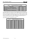
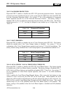
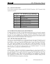
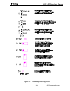
Table 2-18 Terminal Block (6 Position)
Pin Function
1 Telephone Line Ring
2 Telephone Line Tip
3 /Key Out
4 /Key In
5 Ground
6 Spare (See Note Below)
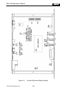
NOTE
In the RTU-282, Pin 6 of the terminal block was the /Squelch In input (also called
“External Signal In” for use with the Squelch Break feature. In the RTU-292, this
input has been moved to a more appropriate location, pin 4 of the P1 Radio
Connector. When retrofitting an RTU-292 into an existing RTU-282 installation,
it’s possible to maintain the existing interface wiring, with the /Squelch line
connected to pin 6 of the Terminal Block. For this to work, an internal jumper
must be added from E1 to E11 on the main PCB. E1 is located just below J12, the
connector that interfaces the terminal block to the main PCB. E11 is at the back of
the PCB, beneath the terminal block connections.
JPS Communications, Inc.
2-14