


7
2
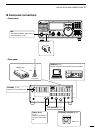
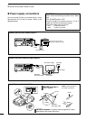
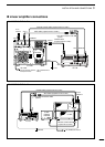
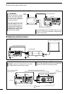
PANEL DESCRIPTION
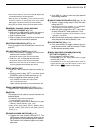
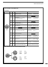
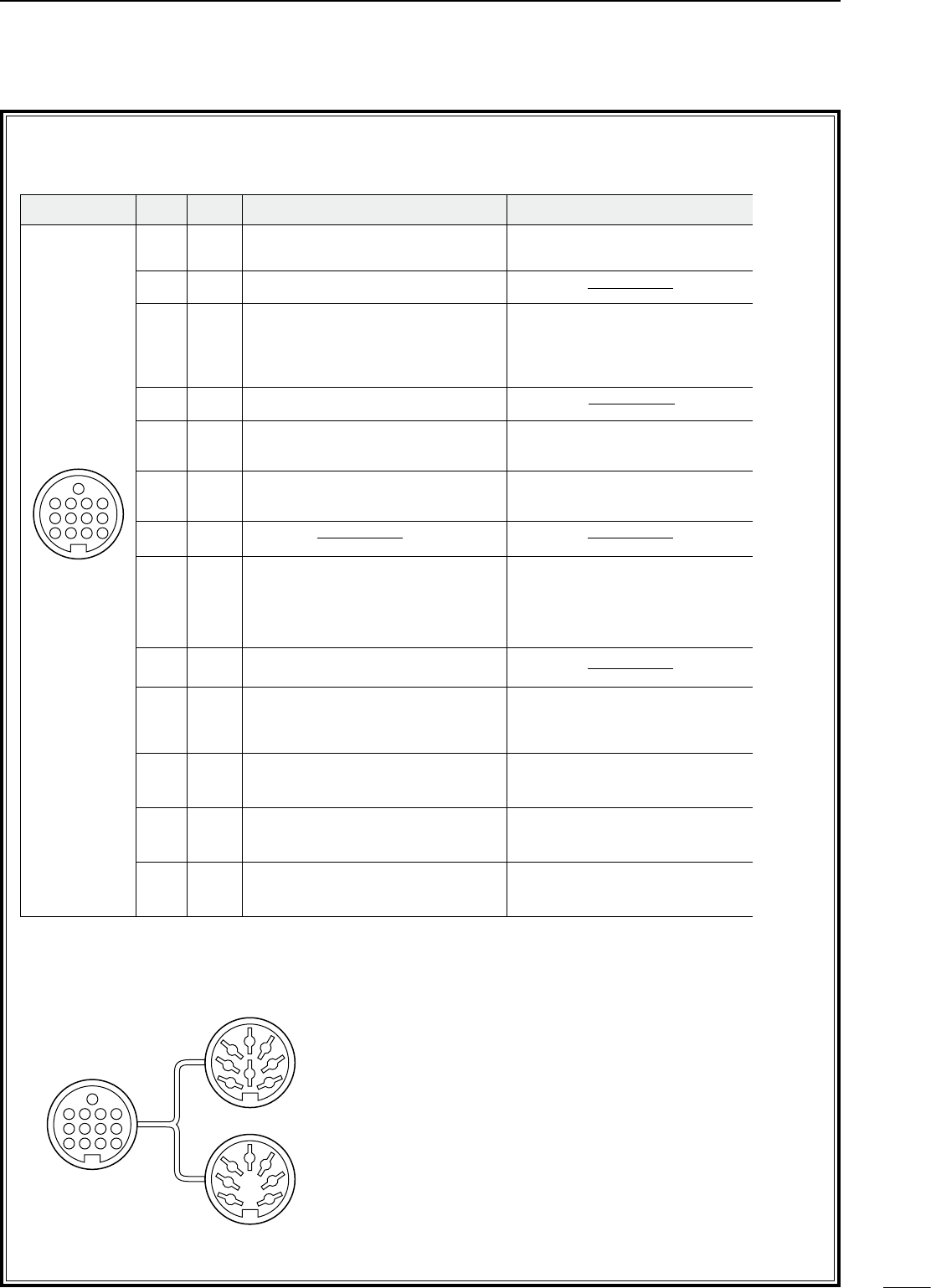
D ACC SOCKET INFORMATION
• ACC socket
• When connecting the ACC conversion cable (OPC-599)
ACC PIN # NAME DESCRIPTION SPECIFICATIONS COLOR
1 8 V Regulated 8 V output.
Output voltage :8 V ±0.3 V
Output current :Less than 10 mA
brown
2 GND Connects to ground. red
3 SEND
Input/output pin.
Goes to ground when transmitting.
When grounded, transmits.
Ground level :–0.5 V to 0.8 V
Input current :Less than 20 mA orange
4 BDT Data line for the optional AT-180. yellow
5 BAND
Band voltage output.
(Varies with amateur band)
Output voltage :0 to 8.0 V green
6 ALC ALC voltage input.
Control voltage :–4 to 0 V
Input impedance :More than 10 kΩ
blue
7 NC purple
8 13.8 V 13.8 V output when power is ON. Output current :Max. 1 A gray
9 TKEY Key line for the AT-180. white
10 FSKK
RTTY keying input.
Ground level :–0.5 to 0.8 V
Input current :Less than 10 mA
black
11 MOD Modulator input.
Input impedance :10 kΩ
Input level :Approx. 100 mV
rms
pink
12 AF
AF detector output.
Fixed, regardless of [AF] position.
Output impedance :4.7 kΩ
Output level :100 to 300 mV rms
light
blue
13 SQLS
Squelch output.
Goes to ground when squelch opens.
SQL open :Less than 0.3 V/5 mA
SQL closed :More than 6.0 V/100 µA
light
green
Rear panel
view
1 2 3 4
8765
9
10 11 12
13
ACC 1
ACC 2
q FSKK t AF
w GND y SQLS
e SEND u 13.8 V
r MOD i ALC
q 8 V t ALC
w GND y NC
e SEND u 13.8 V
r BAND
1
1
2
2
3
3
4
4
8
8
7
7
6
6
5
5
9
10 11 12
13
1
2
3
4
76
5