


15
60
INSTALLATION NOTES
For amateur base station installations, it is
recommended that the forwards clearance in front of
the antenna array is calculated relative to the EIRP
(Effective Isotropic Radiated Power). The clearance
height below the antenna array can be determined in
most cases from the RF power at the antenna input
terminals.
As different exposure limits have been recommended
for different frequencies, a relative table shows a
guideline for installation considerations.
Below 10 MHz, the recommended limits are specified
in terms of V/m or A/m fields as they are likely to fall
within the near-field region. Similarly, at antennae
may be physically short in terms of electrical length
and that the installation will require some antenna
matching device which can create high intensity
magnetic fields. Analysis of such MF installations
is best considered in association with published
guidance notes such as the FCC OET Bulletin 65
Edition 97-01 and its annexes relative to amateur
transmitter installations. Further information can be
found at http://www.arrl.org/
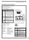
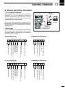
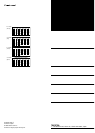
• Typical amateur radio installation
Exposure distance assumes that the predominant
radiation pattern is forwards and that radiation
vertically downwards is at unity gain (sidelobe
suppresion is equal to main lobe gain). This is true of
almost every gain antenna today. Exposed persons
are assumed to be beneath the antenna array and
have a typical height to 1.8 m.
The figures assume the worst case emission of
constant carrier.
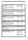
For the bands 10 MHz and higher the following power
density limits are recommended :
10–30 MHz 2 W/sq m
Watts (EIRP)/ Clearance heights
1 2.1 (m)
10 2.8
25 3.4
100 5
1000 12
Watts (EIRP)/ Forward clearance
100 2 (m)
1,000 6.5
10,000 20
100,000 65
In all cases any possible risk depends on the
transmitter being activated for long periods. (actual
recommendation limits are specified as an average
of 6 minutes) Normally the transmitter is not active for
long periods of time. Some radio licenses will require
that a timer circuit automatically cuts the transmitter
after 1–2 minutes etc.
Similarly some types of transmitter, SSB, CW, AM,
etc. have a lower ‘average’ output power and the
perceived risk is even lower.
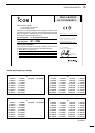
Versions of the IC-718 which display the “CE”
symbol on the serial number seal, comply with
the essential requirements of the European
Radio and Telecommunication Terminal
Directive 1999/5/EC.
This warning symbol indicates that this
equipment operates in non-harmonised
frequency bands and/or may be subject to
licensing conditions in the country of use. Be
sure to check that you have the correct version
of this radio or the correct programming of
this radio, to comply with national licensing
requirement.
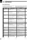
Country Codes
1 Austria AT
2 Belgium BE
3 Bulgaria BG
4 Croatia HR
5 Czech Republic CZ
6 Cyprus CY
7 Denmark DK
8 Estonia EE
9 Finland FI
10 France FR
11 Germany DE
12 Greece GR
13 Hungary HU
14 Iceland IS
15 Ireland IE
16 Italy IT
17 Latvia LV
Country Codes
18 Liechtenstein LI
19 Lithuania LT
20 Luxembourg LU
21 Malta MT
22 Netherlands NL
23 Norway NO
24 Poland PL
25 Portugal PT
26 Romania RO
27 Slovakia SK
28 Slovenia SI
29 Spain ES
30 Sweden SE
31 Switzerland CH
32 Turkey TR
33 United Kingdom GB
List of Country codes (ISO 3166-1)