


8
2
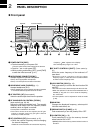
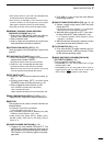
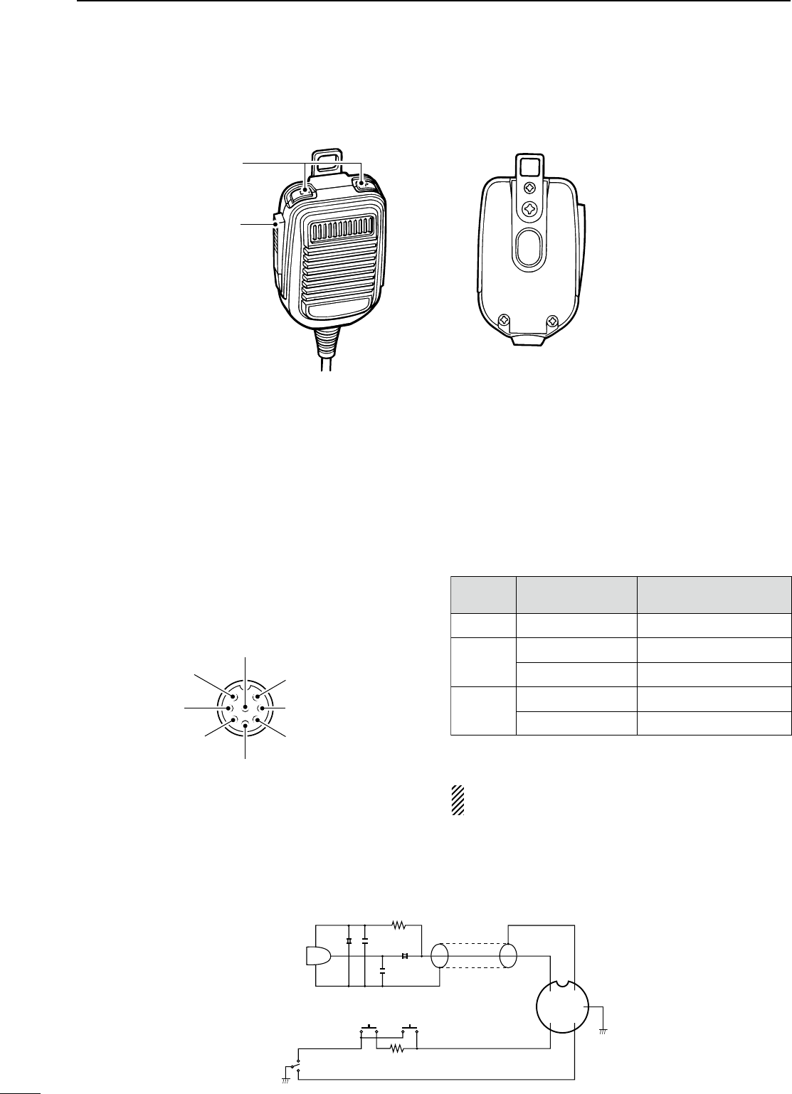
PANEL DESCRIPTION
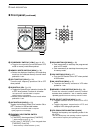
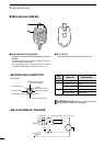
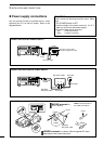
n Microphone (HM-36)
q UP/DOWN SWITCHES [UP]/[DN]
Change the selected readout frequency or memory
channel.
• Continuous pushing changes the frequency or memory
channel number continuously.
• The [UP]/[DN] switch can simulate a key paddle.
Preset in the CW PADDL in initial set mode. (p. 31)
w PTT SWITCH
Push and hold to transmit; release to receive.
q
w
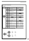
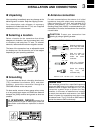
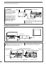
• MICROPHONE CONNECTOR
(Front view)
CAUTION: DO NOT short pin 2 to ground as this
can damage the internal 8 V regulator.
y GND (PTT ground)
t PTT
r Main readout squelch switch
q Microphone input
w +8 V DC output
e Frequency up/down
u GND
(Microphone ground)
i Main readout AF output
(varies with [AF]/[BAL])
Max. 10 mA
Ground
Ground through 470 Ω
“LOW” level
“HIGH” level
+8 V DC output
Frequency up
Frequency down
Squelch open
Squelch closed
[MIC]
PIN NO.
w
e
r
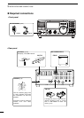
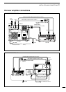
FUNCTION DESCRIPTION
• HM-36 SCHEMATIC DIAGRAM
+
+
q
w
e
r
t
y
u
i
4700p
4700p
10µ
0.33µ
MICROPHONE
MIC
ELEMENT
2k
470
DOWN UP
PTT
RECEIVE
TRANSMIT
MICROPHONE CABLE MICROPHONE PLUG