


53
10
MAINTENANCE
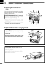
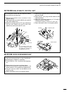
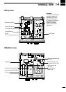
CIRCUITRY FUSE REPLACEMENT
The 13.8 V DC from the DC power cable is applied
to all units in the IC-718 through the circuitry fuse.
This fuse is installed in the MAIN unit.
q Remove the top cover as shown on p. 48
w Replace the circuitry fuse as shown in the
diagram at right.
e Replace the top cover.
FGB 4 A
PA unit
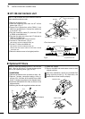
n Fuse replacement
If a fuse blows or the transceiver stops functioning,
try to find the source of the problem, and replace the
damaged fuse with a new, rated fuse.
CAUTION:-DISCONNECT the DC power cable
from the transceiver when changing a fuse.
The IC-718 has 2 types of fuses installed for
transceiver protection.
• DC power cable fuses �������� FGB 20 A
• Circuitry fuse ������������ FGB 4 A
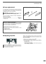
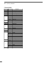
DC POWER CABLE FUSE REPLACEMENT
20 A
fuse
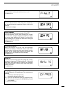
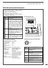
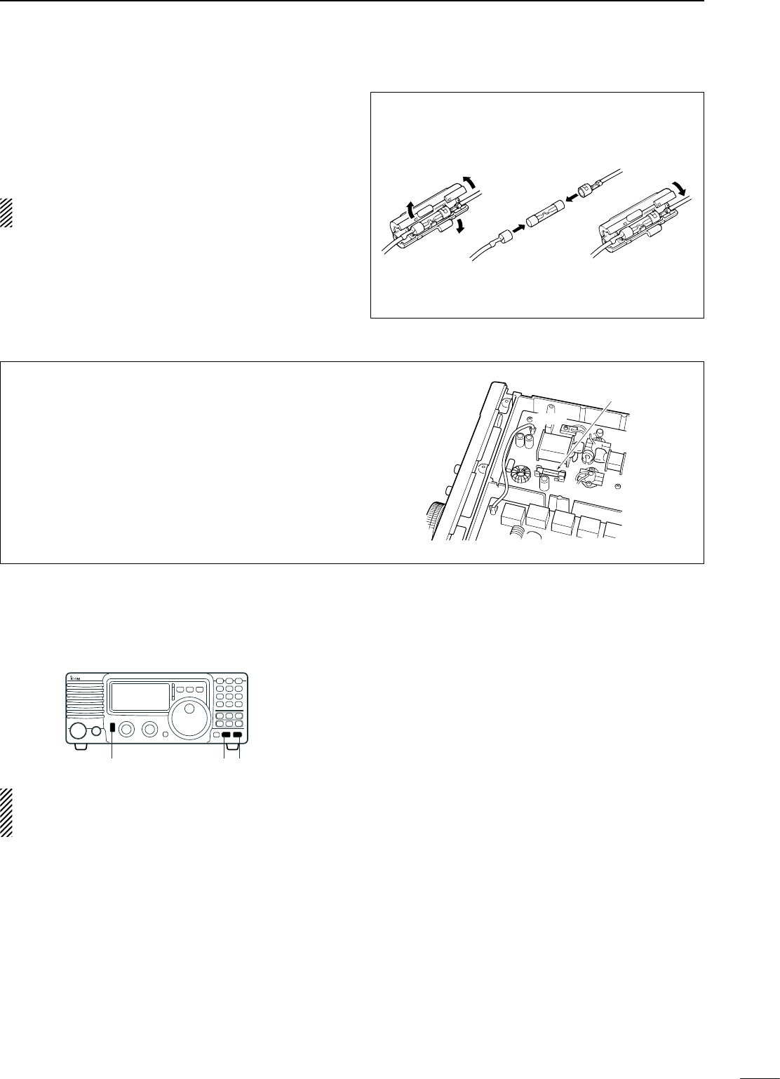
n Resetting the CPU
Resetting CLEARS all programmed contents in
memory channels and returns programmed values
in set mode to their defaults.
When first applying power or when the function
seems to be displaying erroneous information, reset
the CPU as follows:
q Make sure transceiver power is OFF.
w While pushing [UP Y] and [Z DN], push [PWR] to
turn power ON.
• The internal CPU is reset.
• The transceiver displays its initial VFO frequencies
when resetting is complete.
[PWR]
[Z]
[Y]