


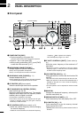
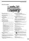
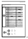
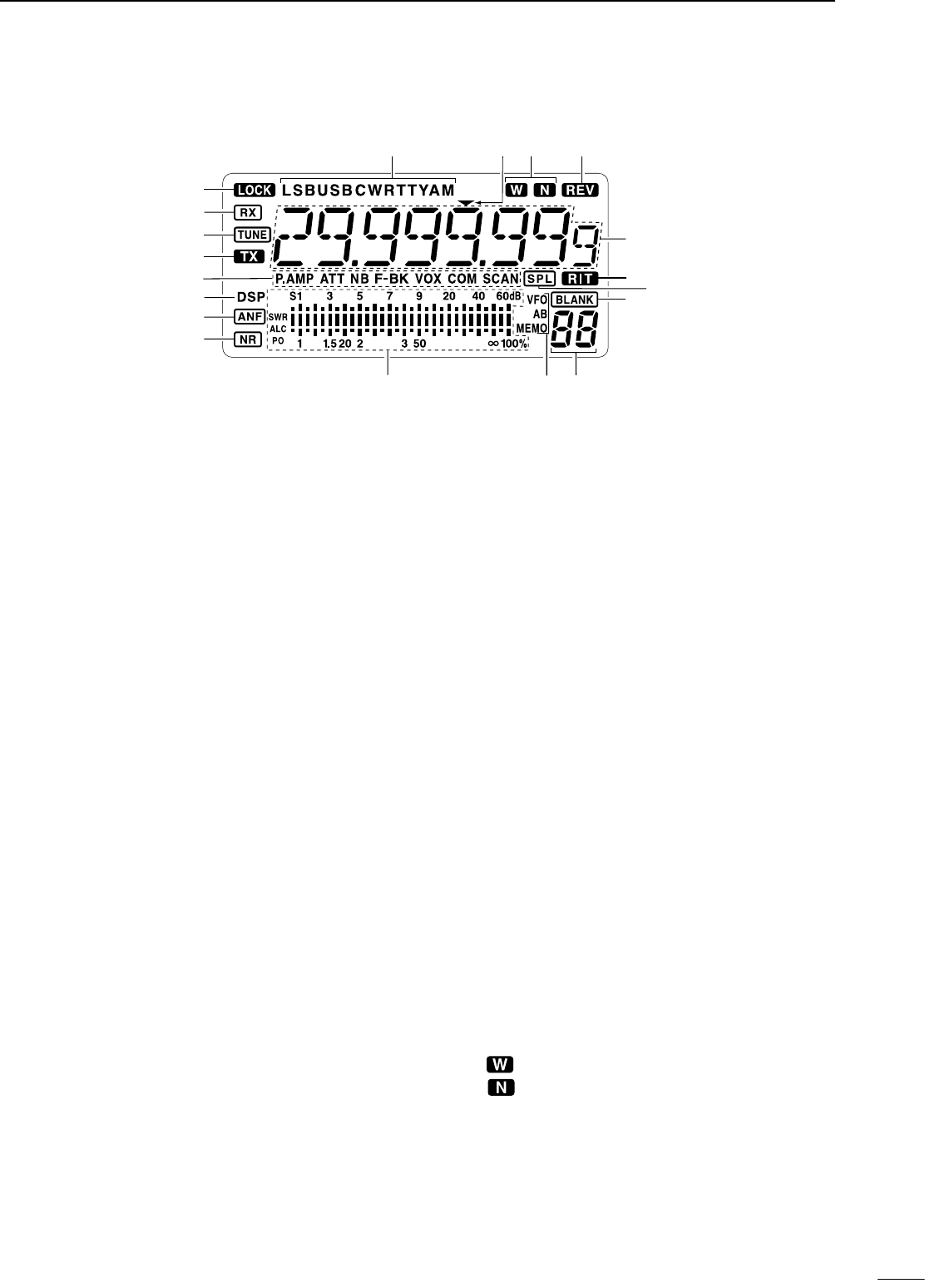
n Function display
q LOCK INDICATOR (p. 19)
Appears when the dial lock function is in use.
w RECEIVE INDICATOR
Appears while receiving a signal or when the
squelch is open.
e TUNE INDICATOR
Appears while the automatic tuning function is
activated.
r TRANSMIT INDICATOR
Appears while transmitting.
t FUNCTION INDICATORS
“P.AMP” appears when antenna preamp is in
use.
“ATT” appears when the attenuator function is in
use.
“NB” appears when the Noise Blanker function
is turned ON.
“BK” appears when the semi break-in function is
selected in quick set mode.
“F-BK” appears when the full break-in function
activates in CW mode. (p. 31)
“VOX” appears when the VOX function is
selected in quick set mode.
“COM” appears when the speech compressor
activates in SSB mode.
“SCAN” appears when the scan function is
activated.
• Flashes when scan is paused.
y DSP UNIT INDICATOR
Appears when an optional UT-106
DSP UNIT is
installed.
u
AUTOMATIC NOTCH FILTER INDICATOR (p. 23)
Appears when the optional Automatic Notch Filter
function is in use.
i NOISE REDUCTION INDICATOR (p. 23)
Appears when the optional Noise Reduction
function is in use.
o SIGNAL/SQL/RF-GAIN METER
Functions as an S-meter while receiving.
Functions as a Power, ALC or SWR meter while
transmitting. (p. 26)
!0 VFO/MEMORY INDICATOR (p. 16)
“VFO A” or “B” appears when VFO mode is
selected.
“MEMO” appears when memory mode is selected.
!1 MEMORY CHANNEL NUMBER READOUT (p. 35)
Shows the selected memory channel number.
!2 BLANK INDICATOR (p. 38)
Shows that the displayed memory channel is not
programmed.
• This indicator appears both in VFO and memory mode.
!3 SPLIT INDICATORS (p. 30)
Appears when the split frequency operation is in
use.
!4 RIT INDICATOR (p. 21)
Appears when the RIT function is in use.
!5 FREQUENCY READOUT
Shows the operating frequency.
!6 REVERSE INDICATOR (p. 20)
Appears when the CW reverse or RTTY reverse
mode is selected.
!7
WIDE/NARROW FILTER INDICATORS (pgs. 24, 25)
“ ” appears when the wide IF filter is selected.
“ ” appears when the narrow IF filter is
selected.
!8 PROGRAMMABLE TUNING STEP INDICATORS
Appears when the programmable tuning step is
selected.
!9 MODE INDICATORS (p. 20)
Indicates the selected operating mode.
5
2
PANEL DESCRIPTION
!9
!6
!7
!8
o
!1!0
r
e
w
!4
!2
!5
!3
t
q
y
u
i