


49
9
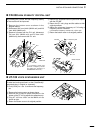
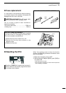
INSTALLATION AND CONNECTIONS
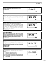
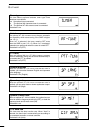
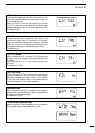
The UT-102 announces the received frequency, mode,
S-meter level and current time in a clear, electronically-
generated voice, in English (or Japanese).
Push [LOCK] for 1 sec. to announce the frequency,
etc.
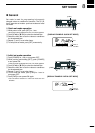
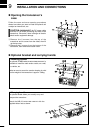
q Remove the bottom cover as shown above.
w
Remove the protective paper attached to the
bottom of the UT-102 to expose the adhesive strip.
e Plug UT-102 into J2501 on the MAIN unit as
shown at right.
r Return the bottom cover to its original position.
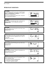
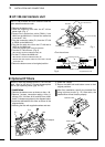
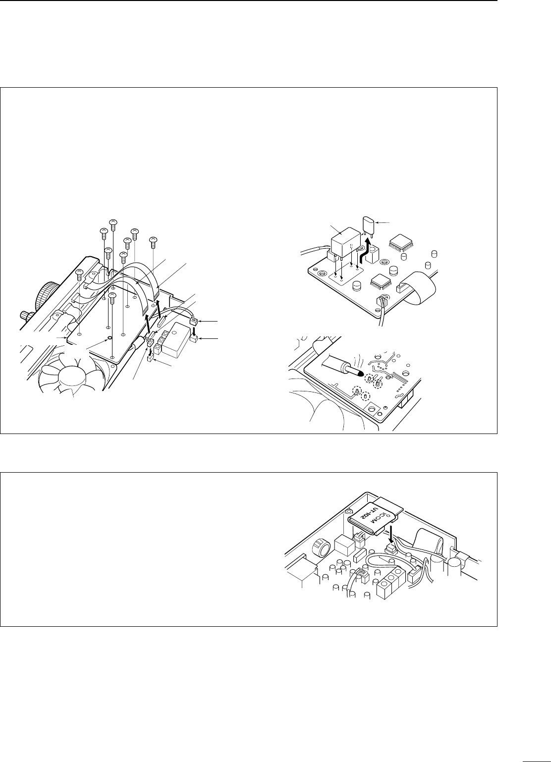
n CR-338 high stability crystal unit
By installing the CR-338, the total frequency stability
of the receiver will be improved.
q Remove the bottom cover as shown in the
diagram before.
w Disconnect W2 from J4401 (MAIN unit) and W3
from J4201 (MAIN unit).
e Remove 9 screws from the PLL unit, disconnect
P4 from J201 (MAIN unit) and P2 from J401
(MAIN unit), then remove the PLL unit.
r Remove the supplied internal crystal and replace
with the CR-338.
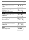
t Return the PLL unit, plugs and flat cables to their
original positions.
y Adjust the reference frequency at C16 using a
frequency counter if desired.
• Connect the frequency counter to P. 2 (PLL unit).
u Return the bottom cover to its original position.
CR-338
Internal crystal
PLL unit
W 3
W 2
J 4201
J 4401
P 4
J 201
J 401
P 2; Frequency check point
(Connect a frequency counter
and adjust the frequency to
64.00000 MHz with C 16.)
C 16
MAIN unit
PLL unit
n UT-102 voice synthesizer unit
Solder 4 leads