


3
2
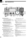
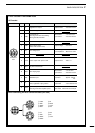
PANEL DESCRIPTION
• Push several times (or push and hold) [√ DN]/[UP ∫]
until desired memory channel appears.
• After pushing [F-INP/ENT], push desired memory
channel number from the keypad, then push [FINP/
ENT] again to select the memory channel directory.
• Push [CH] to exit the memory channel select function.
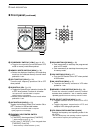
!2 MEMORY CHANNEL (BAND) UP/DOWN
SWITCHES [√ DN]/[UP ∫] (p. 35)
Push one or more times to select the memory
channel, while [MEMO] indicator is blinking.
Push to select a band.
Push to select the quick/initial set mode items
while quick/initial set mode is selected.
!3 ATTENUATOR SWITCH [ATT] (p. 22)
Push to toggle the 20 dB attenuator function ON
and OFF.
!4 TUNER SWITCH [TUNER] (pgs. 28, 29)
Push momentarily to toggle the automatic
antenna tuner function ON/OFF.
• An optional antenna tuner must be connected.
Push for 1 sec. to manually tune the tuner.
• An optional antenna tuner must be connected.
• When the tuner cannot tune the antenna, the tuning
circuit is bypassed automatically after 20 sec.
!5 SET SWITCH [SET]
Push for 1 sec. to enter the quick set mode. (p.
41)
Pushing and holding [SET], and then push
[POWER] to enter the initial set mode. (p. 41)
Push to toggle the meter function; (p. 26)
• PO: indicates the relative RF output power.
• ALC: Indicates ALC level.
• SWR: indicates the SWR over the transmission line.
!6 MIC COMPRESSOR SWITCH [COMP] (p. 27)
Toggles the Mic. compressor function ON and OFF.
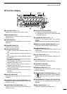
!7 KEYPAD
The keypad can be used for several functions as
discribed below:
• [F-INP/ENT], keypad then [F-INP/ENT].
— Direct frequency input. (pgs. 4, 7)
•
[CH], [F-INP/ENT], keypad then [F-INP/ENT] then [V/M]
— Memory channel selection. (pgs. 4, 35)
• [V/M], [A=B], [A/B], [MW], [M-CL], [M
≈V], [SPL],
[SCAN], [VOX], [NR] (option) and [ANF] (option)
switch. (p. 4)
!8 NOISE BLANKER SWITCH [NB] (p. 22)
Toggles the noise blanker ON and OFF. The
noise blanker reduces pulse-type noise such as
that generated by automobile ignition systems.
This function is not effective against non pulse-
type noise.
Push [NB] for 1 sec to enter the noise blanker
level setting condition.
!9 QUICK TUNING STEP SWITCH [TS] (pgs. 18, 19)
Selects a quick tuning step or turns the quick
tuning step OFF.
• While the quick tuning indicator () is displayed,
the frequency can be changed in kHz step.
While the quick tuning step is OFF, it turns the 1
Hz step ON and OFF when pushed for 1 sec.
• 1 Hz indication appears and the frequency can be
changed in 1 Hz steps.
While the kHz quick tuning step is selected, it enters
tuning step set mode when pushed for 1 sec.
@0 FILTER SWITCH [FIL] (p. 24)
Push momentarily to toggle between the pre-
programmed normal, wide and narrow IF filters
for the selected operating mode.
@1 MODE SWITCHES [LSB/USB]/[CW/CW-R]/
[RTTY/RTTY-R]/[AM] (p. 20)
Push to toggle an operating mode.
• Push[MODE] for 1 sec. during SSB mode to toggle
between LSB or USB.
• Push [MODE] for 2 sec. during CW or RTTY mode, to
toggle between CW and CW reverse or RTTY and
RTTY reverse. “ ” appears on the display.